
What you’ll learn
- 1Explain why an LDR alone cannot be read by Arduino — you need a second resistor.
- 2Wire a voltage divider and predict whether more light raises or lowers the voltage at A0.
- 3Convert
analogRead(0–1023) to a voltage and to a bar width. - 4Add a darkness threshold that could drive an LED or a buzzer.
- LDR / photoresistor
- A resistor whose resistance drops when more light hits it.
- Voltage divider
- Two resistors in series. The middle tap is a fraction of the supply voltage.
- analogRead()
- Arduino function that samples A0–A5 as an integer 0–1023 (10-bit ADC, 0–5 V).
- ADC
- Analog-to-digital converter. 5 V / 1023 ≈ 4.9 mV per step.
- map()
- Processing (and Arduino) helper that remaps a number from one range into another.
Required equipment
| Component | Qty | Purpose |
|---|---|---|
| Arduino Uno | 1 | ADC + serial |
| Photoresistor (LDR) | 1 | Light-dependent resistance |
| 10 kΩ resistor | 1 | Fixed leg of the divider |
| Breadboard + jumpers | 1 | Prototyping |
| USB + both IDEs | 1 | Power, code, display |
Why two resistors?
Arduino’s analog pins measure voltage, not resistance. An LDR by itself is just a rubbery resistor — you have to turn that resistance into a voltage. The cheapest way is a voltage divider: LDR on the 5 V side, 10 kΩ down to GND, tap in the middle to A0.
More light → R_LDR falls → a larger fraction of 5 V appears at A0 → analogRead climbs toward 1023. Cover the sensor with your hand and the number drops.
Build the divider
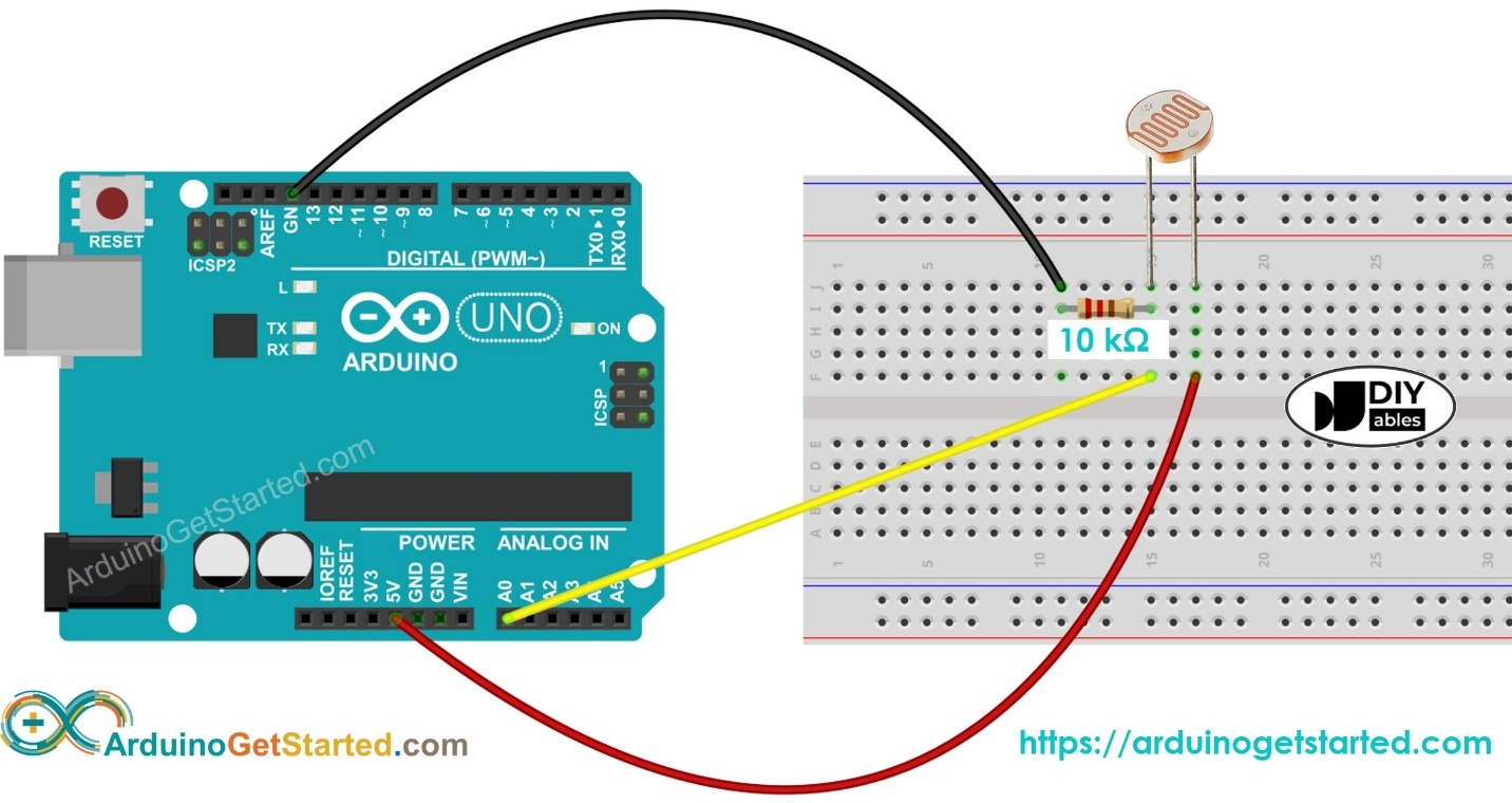
| Connection | Goes to |
|---|---|
| LDR leg 1 | 5V |
| LDR leg 2 | A0 and one leg of 10 kΩ |
| Other 10 kΩ leg | GND |
Arduino — one number, one line
const int sensorPin = A0;

void setup() {
  Serial.begin(9600);
}

void loop() {
  int lightValue = analogRead(sensorPin); // 0 (dark) … 1023 (bright)
  Serial.println(lightValue);
  delay(200);
}
analogRead(A0) returns an integer. Serial.println adds the newline Processing is waiting for. 200 ms is about 5 samples per second — fast enough for a bar, slow enough to read.
Processing — number + bar
import processing.serial.*;

Serial myPort;
int lightLevel = 0;

void setup() {
  size(480, 220);
  printArray(Serial.list());
  myPort = new Serial(this, Serial.list()[0], 9600);
  myPort.bufferUntil('\\n');
}

void draw() {
  background(245);
  fill(20);
  textSize(20);
  text("Light intensity: " + lightLevel, 40, 50);
  fill(0, 100, 255);
  rect(40, 90, map(lightLevel, 0, 1023, 0, 380), 36, 4);
}

void serialEvent(Serial p) {
  String val = trim(p.readStringUntil('\\n'));
  if (val.matches("\\\\d+")) {
    lightLevel = int(val);
  }
}serialEvent and rejects non-numeric junk so a debug line cannot crash the sketch.Student tasks
Troubleshooting
| Problem | Likely cause | Fix |
|---|---|---|
| Value stuck near 0 or 1023. | LDR and 10 kΩ swapped, or A0 not on the junction. | LDR to 5V, 10 kΩ to GND, A0 at the join. |
| Barely changes. | Wrong fixed resistor, or the LDR is in a plastic bag / facing the table. | Point it at the room. Try 4.7 kΩ or 22 kΩ if you have them. |
| Jittery bar. | Mains lights flicker at 100 Hz; ADC noise. | Average 8 readings, or increase delay. |
Exercises
Cover the sensor
Wiring: LDR to 5 V, 10 kΩ to GND, tap to A0. You cover the LDR with your palm. Does analogRead go up or down? Explain in two sentences.
Voltage at A0
R_LDR = 4 kΩ, R_fixed = 10 kΩ, V_in = 5.0 V. Compute V_A0 and the expected analogRead (round to nearest integer).
ADC step size
Arduino’s ADC is 10-bit, 0–5 V. How many millivolts is one analogRead step? If the reading jumps from 400 to 401, how much did the voltage change?
The bar never moves
Processing shows “Light intensity: 0” forever. The Serial Monitor (when Processing is closed) shows numbers. Find the bug.
void draw() {
  if (myPort.available() > 0) {
    String val = myPort.readStringUntil('\\n');
    lightLevel = int(val);
  }
}int(null) and leftover \r will fail. Also, reading in draw can catch half a line.readStringUntil can return null. Windows often sends \r\n, so int("412\r") is 0. Trim and guard. Prefer serialEvent.void serialEvent(Serial p) {
String val = p.readStringUntil('\\n');
if (val == null) return;
val = trim(val);
if (val.matches("\\\\d+")) lightLevel = int(val);
}Night-light firmware
Add an LED on D8 (220 Ω to GND). Turn it on when lightValue < 350 and off otherwise. Keep sending the reading to Processing.
pinMode(8, OUTPUT); in setup. digitalWrite(8, lightValue < 350 ? HIGH : LOW);const int sensorPin = A0;
const int ledPin = 8;
const int DARK = 350;
void setup() {
Serial.begin(9600);
pinMode(ledPin, OUTPUT);
}
void loop() {
int lightValue = analogRead(sensorPin);
digitalWrite(ledPin, lightValue < DARK ? HIGH : LOW);
Serial.println(lightValue);
delay(200);
}Calibrate a classroom scale
You cannot trust 0–1023 as “percent brightness”. Write a 6-step procedure to calibrate your kit: record dark-desk, room, and window-sill readings, then decide how Processing should map those three numbers onto a 0–100 % scale.
dark. 2. Point at the ceiling lights → room. 3. Hold at the window → bright. 4. In Processing, pct = constrain(map(lightLevel, dark, bright, 0, 100), 0, 100). 5. Label the bar with those three marks. 6. Recalibrate if you change the 10 kΩ or the room.Self-check quiz
- Q01
An LDR’s resistance when you shine a torch on it…
- Q02
In this lab’s wiring, more light makes V_A0…
- Q03
analogReadof 0 V is… - Q04
Why not connect the LDR alone from 5 V to A0?
- Q05
A good first fixed resistor for a classroom LDR is…
Real world & extensions
- +Drive an LED on D8 when
lightValue < 300. - +Compare two LDRs (A0 and A1) and draw two bars.
- +Use
saveFrame()every 10 s for a time-lapse of the classroom.
| Subject | Connection |
|---|---|
| Physics | Photoconductivity — photons free charge carriers in the semiconductor. |
| Mathematics | Inverse relationship (roughly): more lux, less ohms. Voltage is a rational function of R. |
| CS | Sampling: 5 Hz is enough for a hand wave, not for a strobe. |
Reflection & conclusion
Did covering the sensor with a notebook change the reading as much as covering it with your hand? Why might that be?
If you swapped LDR and 10 kΩ, how would the “night-light” logic have to change?
Name a product you own that secretly contains this circuit.
You turned resistance into voltage, voltage into a number, and a number into a picture. Lab 04 (ohm meter) is the same divider — you just solve for the unknown resistor.