

Student handbook · workshop edition
Arduino + Processing
Five labs for high-school students. Measure, stream, draw.
2024-2-RS01-KA210-SCH-000271542
Erasmus+ KA210 — Small-scale partnerships in school education





L01
Climate Station — DHT11
Wire a DHT11, send temperature and humidity as one CSV line, and build a live Processing dashboard with bars and threshold alerts — your first two-value serial system.
Objectives
- Install an Arduino library (Adafruit DHT) and explain why libraries exist.
- Wire a digital sensor and name the job of a pull-up resistor.
- Define relative humidity in one sentence a classmate would understand.
- Send two numbers on one serial line and parse them in Processing.
- Add a colour-coded alarm when a reading crosses a threshold.
| Component | Qty | Purpose |
|---|---|---|
| Arduino Uno | 1 | Microcontroller |
| DHT11 sensor | 1 | Temperature + humidity |
| 10 kΩ resistor | 1 | Pull-up (bare 3-pin sensor only) |
| Breadboard + jumpers | 1 | Prototyping |
| USB cable | 1 | Power + serial |
| Arduino IDE + Processing | 1 | Firmware + visualisation |
What you are actually measuring
The DHT11 is a digital sensor. Inside it sits a tiny humidity cell and a thermistor. A chip on the package converts both readings into a timed pulse train. You do not read a voltage on A0 — you ask a library to decode that pulse train on a digital pin.
Relative humidity, in human words
Warm air can hold more water vapour than cold air. Relative humidity is “how full is the air’s water tank right now?” That is why a cold bottle from the fridge sweats: the air next to the glass cools, its tank shrinks, and leftover water condenses.
The serial contract
Arduino and Processing must agree on a format. In this lab the contract is one line, two floats, comma in the middle, newline at the end:
24.50,61.00Wire the sensor
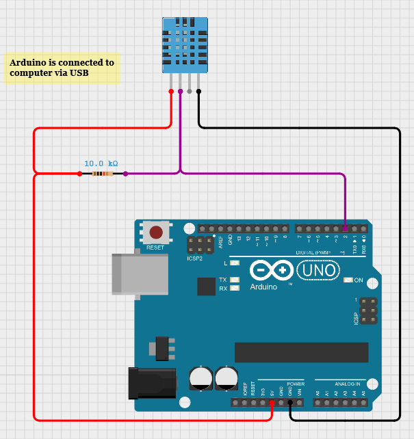
| DHT11 pin | Arduino pin |
|---|---|
| VCC | 5V |
| GND | GND |
| DATA | Digital pin 2 |
Close the Arduino Serial Monitor before you run Processing. Only one program can own the COM port.
- 01In the Arduino IDE open Sketch → Include Library → Manage Libraries.
- 02Search for “DHT sensor library” by Adafruit.
- 03Install it. Accept Adafruit Unified Sensor when asked.
Arduino — read and send
#include "DHT.h"

#define DHTPIN 2
#define DHTTYPE DHT11

DHT dht(DHTPIN, DHTTYPE);

void setup() {
  Serial.begin(9600);
  dht.begin();
}

void loop() {
  float humidity = dht.readHumidity();
  float temperature = dht.readTemperature(); // Celsius

  if (isnan(humidity) || isnan(temperature)) {
    Serial.println("Failed to read from DHT sensor!");
    return;
  }

  Serial.print(temperature);
  Serial.print(",");
  Serial.println(humidity);
  delay(2000);
}Serial.println() adds the newline. Processing will wait for that newline before it tries to parse. Never put a space after the comma unless you also trim it on the other side.Processing — a live dashboard
The original sketch read serial inside `draw()`. That works until a half-line arrives and float() blows up. The version below uses bufferUntil('\n') and serialEvent() — the same pattern you will reuse in every later lab.
import processing.serial.*;

Serial myPort;
float temperature, humidity;

void setup() {
  size(640, 360);
  printArray(Serial.list());
  myPort = new Serial(this, Serial.list()[0], 9600); // change index if needed
  myPort.bufferUntil('\\n');
}

void draw() {
  background(16);
  fill(240);
  textSize(22);
  text("Temperature: " + nf(temperature, 0, 1) + " °C", 40, 60);
  text("Humidity: " + nf(humidity, 0, 1) + " %", 40, 96);

  fill(255, 92, 77);
  rect(40, 140, map(temperature, 0, 50, 0, 520), 28, 4);
  fill(62, 232, 216);
  rect(40, 184, map(humidity, 0, 100, 0, 520), 28, 4);

  if (temperature > 30) {
    fill(255, 80, 80);
    text("HIGH TEMPERATURE", 40, 260);
  } else if (humidity < 30) {
    fill(80, 160, 255);
    text("LOW HUMIDITY", 40, 260);
  }
}

void serialEvent(Serial p) {
  String data = p.readStringUntil('\\n');
  if (data == null) return;
  data = trim(data);
  String[] values = split(data, ",");
  if (values.length == 2) {
    temperature = float(values[0]);
    humidity = float(values[1]);
  }
}serialEvent(). Bars + high-temp / low-humidity alerts included.Serial.list()[0] is whoever Windows listed first — often not the Arduino. Read the printed list. If Processing says the port is busy, close the Arduino Serial Monitor.Exercises
What does the line look like?
Arduino prints Serial.print(temperature); Serial.print(","); Serial.println(humidity); with temperature = 22.4 and humidity = 48. Write the exact characters that travel over USB, including the invisible ones.
println adds a newline (\n). There is no space after the comma.22.40,48.00 followed by \n. (Arduino may print extra zeros — the important part is number,comma,number,newline.)Why a pull-up?
A classmate uses a bare 3-pin DHT11 with only three wires: 5V, GND, DATA. Readings fail at random. Explain, in 4–6 sentences, what a pull-up resistor does on the DATA line and why the module version often works without an extra resistor.
Map a bar
Processing window is 640 px wide. You draw a bar starting at x = 40, and you want 50 °C to fill 520 px. What is map(28, 0, 50, 0, 520)? How wide is the bar at 28 °C?
The NaN trap
This sketch sometimes prints nan,nan and Processing’s bars vanish. Find two bugs and write the corrected loop().
void loop() {
  float h = dht.readHumidity();
  float t = dht.readTemperature();
  Serial.print(t);
  Serial.print(",");
  Serial.println(h);
  delay(200);
}isnan() guard. Bug 2: 200 ms is too fast. Guard and wait 2 s.void loop() {
float h = dht.readHumidity();
float t = dht.readTemperature();
if (isnan(h) || isnan(t)) {
Serial.println("Failed to read from DHT sensor!");
delay(2000);
return;
}
Serial.print(t);
Serial.print(",");
Serial.println(h);
delay(2000);
}Log to CSV
Extend the dashboard so every accepted reading is appended to climate.csv as millis,temp,hum. Create the file in setup() with a header row.
PrintWriter log = createWriter("climate.csv"); then log.println(...) and log.flush().setup(), write a header, then in serialEvent after a successful parse write millis()+","+temperature+","+humidity and flush().PrintWriter log;
void setup() {
// ... serial setup ...
log = createWriter("climate.csv");
log.println("millis,temp,hum");
}
void serialEvent(Serial p) {
String data = trim(p.readStringUntil('\\n'));
String[] v = split(data, ",");
if (v.length != 2) return;
temperature = float(v[0]);
humidity = float(v[1]);
log.println(millis() + "," + temperature + "," + humidity);
log.flush();
}A chart, not a bar
Design (on paper or in code) a 2-minute scrolling chart of temperature. List: the data structure you store, how many points, how you map time to x and temperature to y, and what happens when the array is full.
append() + subset() to drop the oldest point.for i in 0..n-2: a[i]=a[i+1]) and write the new sample at the end. Draw with beginShape() / vertex() / endShape().Quiz
- Q01
The DHT11 talks to Arduino on…
- Q02
Relative humidity is 100 %. What does that mean?
- Q03
Why check
isnan()? - Q04
Which serial line matches the contract of this lab?
- Q05
Processing should read serial in…
- Q06
A 3-pin DHT11 **module** usually does not need an extra 10 kΩ because…
L02
Light Meter — LDR
Build a voltage divider with a photoresistor, read 0–1023 on A0, and turn classroom light into a live bar — the same circuit idea you will reuse for the ohm meter.
Objectives
- Explain why an LDR alone cannot be read by Arduino — you need a second resistor.
- Wire a voltage divider and predict whether more light raises or lowers the voltage at A0.
- Convert
analogRead(0–1023) to a voltage and to a bar width. - Add a darkness threshold that could drive an LED or a buzzer.
| Component | Qty | Purpose |
|---|---|---|
| Arduino Uno | 1 | ADC + serial |
| Photoresistor (LDR) | 1 | Light-dependent resistance |
| 10 kΩ resistor | 1 | Fixed leg of the divider |
| Breadboard + jumpers | 1 | Prototyping |
| USB + both IDEs | 1 | Power, code, display |
Why two resistors?
Arduino’s analog pins measure voltage, not resistance. An LDR by itself is just a rubbery resistor — you have to turn that resistance into a voltage. The cheapest way is a voltage divider: LDR on the 5 V side, 10 kΩ down to GND, tap in the middle to A0.
More light → R_LDR falls → a larger fraction of 5 V appears at A0 → analogRead climbs toward 1023. Cover the sensor with your hand and the number drops.
Build the divider
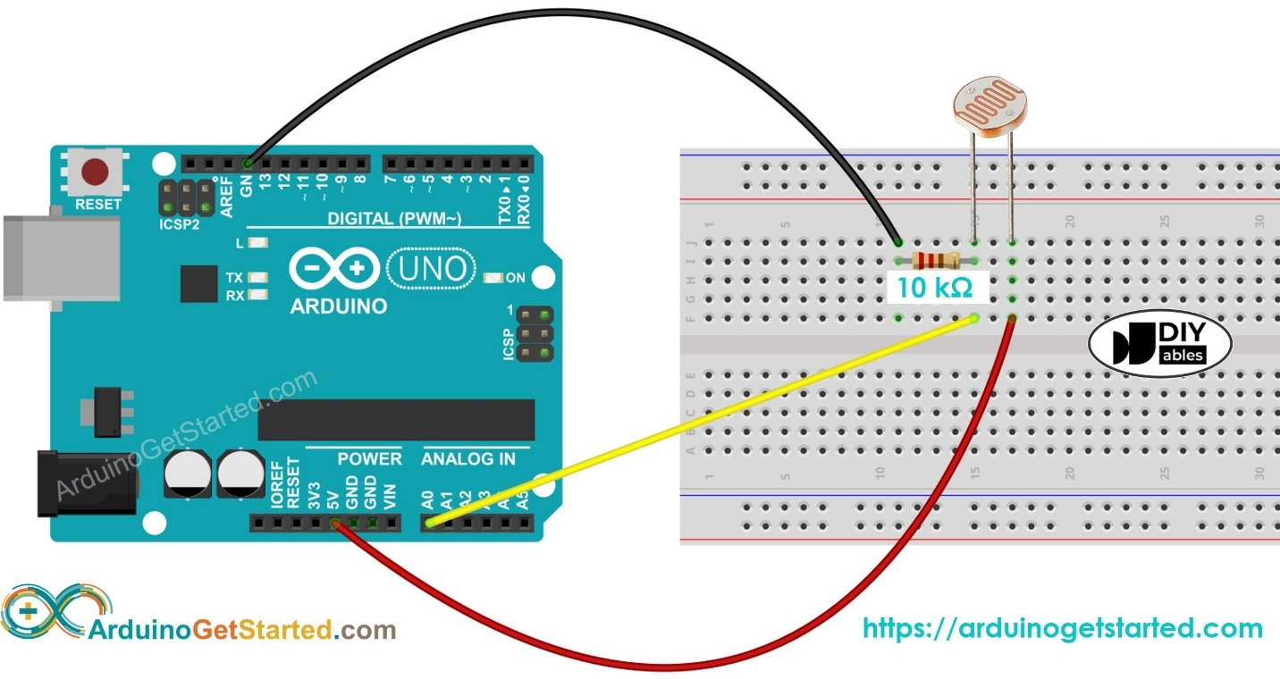
| Connection | Goes to |
|---|---|
| LDR leg 1 | 5V |
| LDR leg 2 | A0 and one leg of 10 kΩ |
| Other 10 kΩ leg | GND |
Arduino — one number, one line
const int sensorPin = A0;

void setup() {
  Serial.begin(9600);
}

void loop() {
  int lightValue = analogRead(sensorPin); // 0 (dark) … 1023 (bright)
  Serial.println(lightValue);
  delay(200);
}
analogRead(A0) returns an integer. Serial.println adds the newline Processing is waiting for. 200 ms is about 5 samples per second — fast enough for a bar, slow enough to read.
Processing — number + bar
import processing.serial.*;

Serial myPort;
int lightLevel = 0;

void setup() {
  size(480, 220);
  printArray(Serial.list());
  myPort = new Serial(this, Serial.list()[0], 9600);
  myPort.bufferUntil('\\n');
}

void draw() {
  background(245);
  fill(20);
  textSize(20);
  text("Light intensity: " + lightLevel, 40, 50);
  fill(0, 100, 255);
  rect(40, 90, map(lightLevel, 0, 1023, 0, 380), 36, 4);
}

void serialEvent(Serial p) {
  String val = trim(p.readStringUntil('\\n'));
  if (val.matches("\\\\d+")) {
    lightLevel = int(val);
  }
}serialEvent and rejects non-numeric junk so a debug line cannot crash the sketch.Exercises
Cover the sensor
Wiring: LDR to 5 V, 10 kΩ to GND, tap to A0. You cover the LDR with your palm. Does analogRead go up or down? Explain in two sentences.
Voltage at A0
R_LDR = 4 kΩ, R_fixed = 10 kΩ, V_in = 5.0 V. Compute V_A0 and the expected analogRead (round to nearest integer).
ADC step size
Arduino’s ADC is 10-bit, 0–5 V. How many millivolts is one analogRead step? If the reading jumps from 400 to 401, how much did the voltage change?
The bar never moves
Processing shows “Light intensity: 0” forever. The Serial Monitor (when Processing is closed) shows numbers. Find the bug.
void draw() {
  if (myPort.available() > 0) {
    String val = myPort.readStringUntil('\\n');
    lightLevel = int(val);
  }
}int(null) and leftover \r will fail. Also, reading in draw can catch half a line.readStringUntil can return null. Windows often sends \r\n, so int("412\r") is 0. Trim and guard. Prefer serialEvent.void serialEvent(Serial p) {
String val = p.readStringUntil('\\n');
if (val == null) return;
val = trim(val);
if (val.matches("\\\\d+")) lightLevel = int(val);
}Night-light firmware
Add an LED on D8 (220 Ω to GND). Turn it on when lightValue < 350 and off otherwise. Keep sending the reading to Processing.
pinMode(8, OUTPUT); in setup. digitalWrite(8, lightValue < 350 ? HIGH : LOW);const int sensorPin = A0;
const int ledPin = 8;
const int DARK = 350;
void setup() {
Serial.begin(9600);
pinMode(ledPin, OUTPUT);
}
void loop() {
int lightValue = analogRead(sensorPin);
digitalWrite(ledPin, lightValue < DARK ? HIGH : LOW);
Serial.println(lightValue);
delay(200);
}Calibrate a classroom scale
You cannot trust 0–1023 as “percent brightness”. Write a 6-step procedure to calibrate your kit: record dark-desk, room, and window-sill readings, then decide how Processing should map those three numbers onto a 0–100 % scale.
dark. 2. Point at the ceiling lights → room. 3. Hold at the window → bright. 4. In Processing, pct = constrain(map(lightLevel, dark, bright, 0, 100), 0, 100). 5. Label the bar with those three marks. 6. Recalibrate if you change the 10 kΩ or the room.Quiz
- Q01
An LDR’s resistance when you shine a torch on it…
- Q02
In this lab’s wiring, more light makes V_A0…
- Q03
analogReadof 0 V is… - Q04
Why not connect the LDR alone from 5 V to A0?
- Q05
A good first fixed resistor for a classroom LDR is…
L03
Distance, Servo & Radar
Four linked builds: measure distance with an HC-SR04, drive an SG90 from Processing buttons, let distance aim the servo, then scan 180° and draw a radar.
Objectives
- Derive distance from echo time and the speed of sound.
- Trigger the HC-SR04 correctly (10 µs pulse) and use a
pulseIntimeout. - Send START / STOP from Processing and sweep a servo without freezing the loop.
- Combine angle + distance into a polar plot (radar).
| Component | Qty | Purpose |
|---|---|---|
| Arduino Uno | 1 | Timing + servo PWM |
| HC-SR04 | 1 | Distance |
| SG90 servo | 1 | Sweep / aim |
| Plastic holder | 1 | Mount the sensor on the horn |
| USB + both IDEs | 1 | Control + radar display |
The echo is a clock
The HC-SR04 clicks at ~40 kHz — too high to hear. The click hits a wall and comes back. Distance is half the trip, because the sound went there and back.
Exercise A — distance on a bar
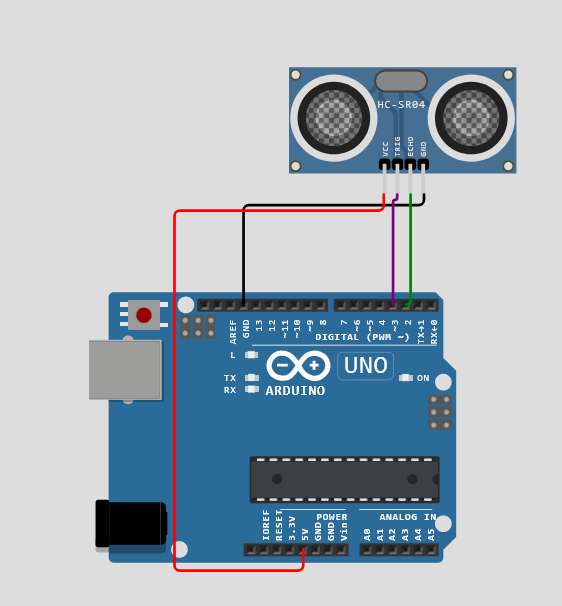
| HC-SR04 | Arduino |
|---|---|
| VCC | 5V |
| GND | GND |
| TRIG | D3 |
| ECHO | D2 |
const int trigPin = 3;
const int echoPin = 2;

void setup() {
  Serial.begin(9600);
  pinMode(trigPin, OUTPUT);
  pinMode(echoPin, INPUT);
}

void loop() {
  digitalWrite(trigPin, LOW);
  delayMicroseconds(2);
  digitalWrite(trigPin, HIGH);
  delayMicroseconds(10);
  digitalWrite(trigPin, LOW);

  long duration = pulseIn(echoPin, HIGH, 30000); // µs, 30 ms timeout
  float distance = duration * 0.0343 / 2.0;
  Serial.println(distance);
  delay(80);
}pulseIn now has a 30 000 µs timeout so a missing echo cannot freeze the board for a full second.import processing.serial.*;
Serial myPort;
float distance;
void setup() {
size(640, 200);
printArray(Serial.list());
myPort = new Serial(this, Serial.list()[0], 9600);
myPort.bufferUntil('\\n');
}
void draw() {
background(16);
fill(240);
textSize(22);
text("Distance: " + nf(distance, 0, 1) + " cm", 36, 48);
fill(62, 232, 216);
rect(36, 80, map(constrain(distance, 0, 200), 0, 200, 0, width - 80), 36, 4);
}
void serialEvent(Serial p) {
String data = trim(p.readStringUntil('\\n'));
distance = float(data);
}Exercise B — START / STOP from Processing
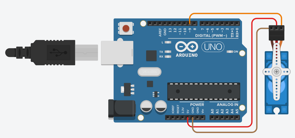
| Servo wire | Arduino |
|---|---|
| Brown / black (GND) | GND |
| Red (VCC) | 5V |
| Orange / yellow (signal) | D9 |
The original handbook swept with two blocking for loops. STOP sat in the serial buffer until the horn finished 180°. The sketch below moves one degree per loop and checks serial every time.
#include <Servo.h>

Servo servo;
bool sweeping = false;
int angle = 0;
int dir = 1;

void setup() {
  Serial.begin(9600);
  servo.attach(9);
  servo.write(0);
}

void loop() {
  if (Serial.available()) {
    String command = Serial.readStringUntil('\\n');
    command.trim();
    if (command == "START") sweeping = true;
    else if (command == "STOP") sweeping = false;
  }

  if (sweeping) {
    angle += dir;
    if (angle >= 180) { angle = 180; dir = -1; }
    if (angle <= 0) { angle = 0; dir = 1; }
    servo.write(angle);
    delay(12);
  }
}import processing.serial.*;
Serial myPort;
boolean isSweeping = false;
void setup() {
size(420, 220);
printArray(Serial.list());
myPort = new Serial(this, Serial.list()[0], 9600);
textAlign(CENTER, CENTER);
}
void draw() {
background(24);
fill(230);
textSize(18);
text("Servo control", width / 2, 36);
drawButton("START", 70, 100, isSweeping);
drawButton("STOP", 240, 100, !isSweeping);
}
void drawButton(String label, int x, int y, boolean active) {
fill(active ? color(62, 200, 140) : color(50));
rect(x, y, 110, 48, 8);
fill(active ? 10 : 230);
text(label, x + 55, y + 24);
}
void mousePressed() {
if (mouseX > 70 && mouseX < 180 && mouseY > 100 && mouseY < 148) {
myPort.write("START\\n");
isSweeping = true;
} else if (mouseX > 240 && mouseX < 350 && mouseY > 100 && mouseY < 148) {
myPort.write("STOP\\n");
isSweeping = false;
}
}Exercise C — distance aims the servo
A common kit build: if something is closer than 50 cm, turn the horn to 90°; otherwise park at 0°. TRIG/ECHO move to D6/D7 in this example so you can keep the servo on D9.
#include <Servo.h>

const int TRIG_PIN = 6;
const int ECHO_PIN = 7;
const int SERVO_PIN = 9;
const int THRESHOLD_CM = 50;

Servo servo;

void setup() {
  Serial.begin(9600);
  pinMode(TRIG_PIN, OUTPUT);
  pinMode(ECHO_PIN, INPUT);
  servo.attach(SERVO_PIN);
  servo.write(0);
}

void loop() {
  digitalWrite(TRIG_PIN, HIGH);
  delayMicroseconds(10);
  digitalWrite(TRIG_PIN, LOW);

  float duration = pulseIn(ECHO_PIN, HIGH, 30000);
  float distance = 0.017 * duration;

  servo.write(distance > 0 && distance < THRESHOLD_CM ? 90 : 0);

  Serial.print("distance: ");
  Serial.print(distance);
  Serial.println(" cm");
  delay(80);
}distance: 42.0 cm — not a bare number. Write a Processing sketch that strips the text, shows the number, draws a bar, and could later send START/STOP if you add buttons.Exercise D — radar scanner
Mount the HC-SR04 on the servo horn. Arduino sweeps 0–180°, measures, and prints angle,distance. Processing plots each hit in polar coordinates. This is a favourite Digital Challenge project.
#include <Servo.h>

Servo myServo;
const int trigPin = 9;
const int echoPin = 10;

void setup() {
  Serial.begin(9600);
  myServo.attach(6);
  pinMode(trigPin, OUTPUT);
  pinMode(echoPin, INPUT);
}

void loop() {
  for (int angle = 0; angle <= 180; angle += 2) {
    myServo.write(angle);
    delay(40);
    digitalWrite(trigPin, LOW);
    delayMicroseconds(2);
    digitalWrite(trigPin, HIGH);
    delayMicroseconds(10);
    digitalWrite(trigPin, LOW);
    long duration = pulseIn(echoPin, HIGH, 30000);
    float distance = duration * 0.0343 / 2.0;
    Serial.print(angle);
    Serial.print(",");
    Serial.println(distance);
  }
}pulseIn. Prints angle,distance once per step. After 180° the loop restarts at 0 — add a down-sweep if you want a smooth return.import processing.serial.*;
Serial myPort;
int angle;
float distance;
void setup() {
size(640, 400);
printArray(Serial.list());
myPort = new Serial(this, Serial.list()[0], 9600);
myPort.bufferUntil('\\n');
background(6);
}
void draw() {
// fade so old blips die out
noStroke();
fill(6, 18);
rect(0, 0, width, height);
float r = map(constrain(distance, 0, 100), 0, 100, 0, 260);
float x = width / 2 + r * cos(radians(angle));
float y = height - 20 - r * sin(radians(angle));
fill(62, 232, 216);
ellipse(x, y, 6, 6);
}
void serialEvent(Serial p) {
String data = trim(p.readStringUntil('\\n'));
String[] parts = split(data, ",");
if (parts.length == 2) {
angle = int(parts[0]);
distance = float(parts[1]);
}
}Exercises
How far?
pulseIn returns 2915 µs. Using 343 m/s, how far is the object in centimetres?
Cold classroom
The code assumes 343 m/s. The room is 10 °C (v ≈ 337.4 m/s). A wall is truly 100 cm away. What distance does the sketch print, and what is the % error?
STOP is late
A student used the original blocking sweep. Explain in 4 sentences why STOP waits, then write the non-blocking idea in two lines of pseudocode.
for (angle = 0; angle <= 180; angle++) { servo.write(angle); delay(10); } does not call Serial.available() for 1.8 s. The STOP line sits in the UART buffer. Pseudocode: each loop: read serial → update sweeping flag → if sweeping, angle += dir, write once, delay 12 ms.Parse a messy line
Arduino prints distance: 42.0 cm. Write serialEvent that extracts 42.0. Do not crash on distance: 0.0 cm or a timeout line.
splitTokens(data, " :cm") or find the first number with a small scan.void serialEvent(Serial p) {
String data = trim(p.readStringUntil('\\n'));
String[] bits = splitTokens(data, " :cm");
for (int i = 0; i < bits.length; i++) {
if (bits[i].length() > 0 && Character.isDigit(bits[i].charAt(0))) {
distance = float(bits[i]);
break;
}
}
}Polar plot one point
Window 600×600, origin at (300, 580). Angle 45°, distance 50 cm mapped onto r = 0…250 for 0…100 cm. Compute x and y of the blip.
Parking sensor UX
Design a Processing UI for a reversing sensor: three zones (<30, 30–80, >80 cm), colour, optional beep, and a frozen “HOLD” button that stops the servo. Sketch the layout and list the serial messages in both directions.
angle,distance or just distance. PC → Arduino: START, STOP, maybe HOLD. UI: big number, coloured bar, zone chips, mute toggle. Beep interval shortens as distance falls (map 80→30 cm onto 800→80 ms). HOLD sends STOP and freezes the last bar.Quiz
- Q01
We divide the echo time by 2 because…
- Q02
A 10 µs HIGH on TRIG…
- Q03
pulseIn(pin, HIGH)with no timeout can… - Q04
The original START/STOP sweep ignored STOP because…
- Q05
Radar serial format in this lab is…
- Q06
x = r cos θ, y = r sin θ is…
L04
Ohm Meter
Use a known resistor as a reference, read the divider voltage, apply Ohm’s law, and show the unknown value in Processing — including kΩ / MΩ units and an out-of-range warning.
Objectives
- State Ohm’s law and the divider formula that matches this wiring.
- Explain why the unknown resistor sits on the 5 V side in the handbook figure.
- Compute R_x from V_A0 and discuss when the measurement is accurate.
- Guard against a missing resistor (open circuit → do not divide by zero).
| Component | Qty | Purpose |
|---|---|---|
| Arduino Uno | 1 | ADC |
| Known resistor (1 kΩ) | 1 | Reference |
| Unknown resistor | 1 | The one you measure |
| Breadboard + jumpers | 1 | Divider |
| USB + both IDEs | 1 | Display |
One formula — the one that matches the figure
The original handbook wrote two opposite formulas. The Fritzing figure labels the unknown on the 5 V side and the known toward GND. The firmware below follows that figure.
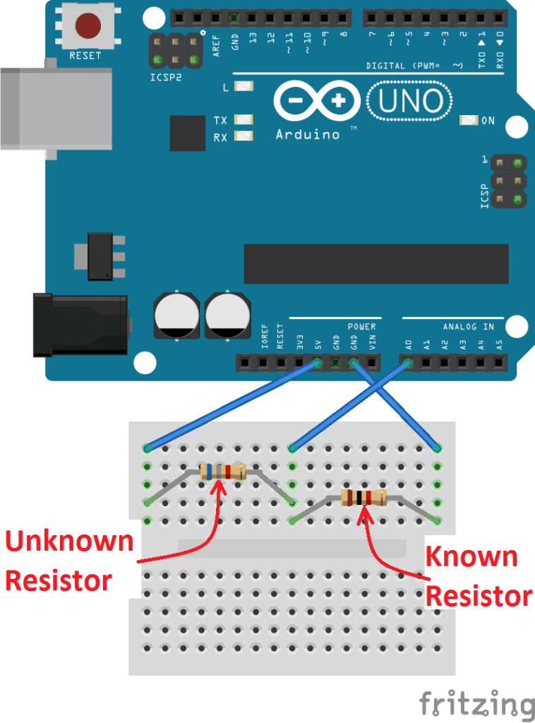
Accuracy is best when R_x ≈ R_known. If you measure 1 MΩ against a 1 kΩ reference, V_A0 is a few millivolts — one ADC step is a huge error. Choose a known resistor in the same decade as the unknown.
Arduino — solve for R_x
| Lead | Goes to |
|---|---|
| Unknown resistor | 5V → A0 (junction) |
| Known 1 kΩ | A0 → GND |
| A0 | The junction of the two resistors |
const int analogPin = A0;
const float Vin = 5.0;
const float Rknown = 1000.0; // ohms — change if you use another reference

void setup() {
  Serial.begin(9600);
}

void loop() {
  int raw = analogRead(analogPin);
  if (raw < 2) {          // open circuit / missing unknown
    Serial.println(-1);
    delay(400);
    return;
  }
  float Vout = (raw * Vin) / 1023.0;
  float Rx = Rknown * (Vin / Vout - 1.0);
  Serial.println(Rx);
  delay(400);
}Processing — units and range
import processing.serial.*;

Serial myPort;
float resistance = 0;

void setup() {
  size(520, 240);
  printArray(Serial.list());
  myPort = new Serial(this, Serial.list()[0], 9600);
  myPort.bufferUntil('\\n');
}

void draw() {
  background(18);
  fill(240);
  textSize(20);
  text("Measured resistance", 36, 56);
  textSize(36);
  if (resistance < 0) {
    fill(255, 92, 77);
    text("OPEN — check wiring", 36, 120);
  } else {
    text(formatOhms(resistance), 36, 120);
  }
}

String formatOhms(float r) {
  if (r >= 1e6) return nf(r / 1e6, 1, 2) + " MΩ";
  if (r >= 1000) return nf(r / 1000, 1, 2) + " kΩ";
  return nf(r, 1, 1) + " Ω";
}

void serialEvent(Serial p) {
  String val = trim(p.readStringUntil('\\n'));
  resistance = float(val);
}
Exercises
Do the algebra
R_known = 1000 Ω, V_A0 = 2.0 V, V_in = 5.0 V, unknown on the 5 V side. Find R_x.
What does the ADC see?
R_x = 2.2 kΩ, R_known = 1.0 kΩ, unknown on 5 V side. Compute V_A0 and analogRead.
Why not measure 1 MΩ with 1 kΩ?
In 5–6 sentences, explain why a 1 kΩ reference is a bad choice for a 1 MΩ unknown. Mention V_A0 and one ADC step (≈ 4.9 mV).
Infinity on the screen
Someone unplugged the unknown resistor. Processing prints Infinity Ω. Point to the line that blew up and write the guard.
float Vout = (raw * 5.0) / 1023.0;
float Rx = 1000.0 * (5.0 / Vout - 1.0);
Serial.println(Rx);5.0 / Vout is infinity. Send a sentinel (−1) and let Processing print OPEN.if (raw < 2) { Serial.println(-1); return; }
float Vout = (raw * 5.0) / 1023.0;
Serial.println(1000.0 * (5.0 / Vout - 1.0));Range picker
Processing keys 1, 2, 3 send "K,1000\n", "K,10000\n", "K,100000\n". Arduino updates Rknown when a line starts with K. Keep printing R_x as a number.
Serial.readStringUntil and startsWith("K,"). On Processing keyPressed().float Rknown = 1000. Each loop, if serial is available, read a line; if it starts with K,, parse the rest as the new known value. Processing’s keyPressed writes the matching command.Quiz
- Q01
With unknown on the 5 V side, R_x equals…
- Q02
Best accuracy when…
- Q03
A 1 kΩ ±5 % reference means R_known might be…
- Q04
Sending −1 over serial in this lab means…
- Q05
Fingers on the leads make the reading…
L05
Soil Moisture
Read a soil probe on A0, remember that wet usually means a **lower** number, calibrate three cups, and build a live moisture bar — the last workshop system.
Objectives
- Wire a 3-pin soil probe (VCC, GND, AOUT→A0) and read it.
- Calibrate dry / damp / wet for the probe on your desk — do not trust a datasheet.
- Invert
map()so a falling analog value still grows a “wetter” bar. - Design an alert that would later drive a pump or a buzzer.
| Component | Qty | Purpose |
|---|---|---|
| Arduino Uno | 1 | ADC |
| Soil moisture probe | 1 | Capacitive v1.2 or resistive fork |
| Three cups of soil / kitchen towel | 3 | Dry, damp, wet calibration |
| USB + both IDEs | 1 | Display |
Wet is usually a smaller number
Most classroom probes output a higher voltage in dry media and a lower voltage when wet. analogRead of ~800–950 is “leave it”, ~500 is “fine”, ~300 is “soaked”. Your board will differ. That is why this lab starts with three cups, not with a formula.
Arduino — send the raw reading
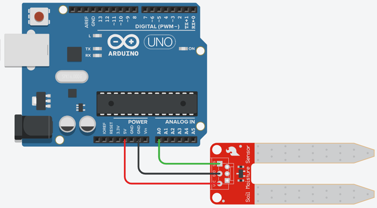
| Probe pin | Arduino |
|---|---|
| VCC | 5V (or 3.3 V if the module insists) |
| GND | GND |
| AOUT | A0 |
const int sensorPin = A0;

void setup() {
  Serial.begin(9600);
}

void loop() {
  int moisture = analogRead(sensorPin); // often 1023 dry → ~300 wet
  Serial.println(moisture);
  delay(300);
}Processing — invert the bar
map(moisture, 1023, 300, 0, 360) reads backwards on purpose: a falling ADC still grows a “wetter” bar. Replace 1023 and 300 with your dry and wet averages.
import processing.serial.*;

Serial myPort;
int moisture = 0;
int DRY = 900;  // replace after calibration
int WET = 320;

void setup() {
  size(500, 240);
  printArray(Serial.list());
  myPort = new Serial(this, Serial.list()[0], 9600);
  myPort.bufferUntil('\\n');
}

void draw() {
  background(18);
  float pct = constrain(map(moisture, DRY, WET, 0, 100), 0, 100);
  fill(230);
  textSize(20);
  text("Soil moisture  " + moisture + "   " + int(pct) + " %", 32, 48);

  fill(pct < 25 ? color(255, 92, 77) : color(124, 255, 178));
  rect(32, 90, map(pct, 0, 100, 0, 420), 40, 4);
  if (pct < 25) {
    fill(255, 92, 77);
    text("DRY — water the plant", 32, 170);
  }
}

void serialEvent(Serial p) {
  String val = trim(p.readStringUntil('\\n'));
  if (val.matches("\\\\d+")) moisture = int(val);
}
Exercises
Which way does the number go?
You dip a typical classroom probe from dry potting mix into a wet cup. Does analogRead rise or fall? Why did the Processing bar still get longer in the starter sketch?
map(moisture, DRY, WET, 0, 100) has DRY > WET, so a smaller input maps to a larger output. The bar follows wetness, not voltage.Percent wet
Your calibration: DRY = 880, WET = 340. A reading is 610. What % wet is constrain(map(610, 880, 340, 0, 100), 0, 100)?
Three-cup lab sheet
Fill in a table: medium (dry soil, damp soil, wet soil, cup of water, open air) × 10 readings × average. Then choose DRY and WET for your Processing sketch. Photograph the table or type it into the handbook.
- 01Wipe the probe between cups.
- 02Wait 8 seconds after dipping before you record.
- 03Average 10 samples — do not pick the prettiest one.
- 04Open air is not the same as dry soil. Use dry soil as DRY if the plant will live in soil.
Smooth the jitter
Average the last 8 analog readings on Arduino before printing. Keep the serial contract as one integer per line.
const int N = 8;
int buf[N];
int i = 0;

void loop() {
  buf[i] = analogRead(A0);
  i = (i + 1) % N;
  long sum = 0;
  for (int k = 0; k < N; k++) sum += buf[k];
  Serial.println(sum / N);
  delay(50);
}Don’t chatter the pump
A single threshold if (reading > 700) pumpOn(); else pumpOff(); will flip the relay every few hundred milliseconds as the reading hovers. Design hysteresis: pick two numbers and write the if logic. Explain why plants (and relays) prefer this.
Quiz
- Q01
On most classroom probes, wet soil makes
analogRead… - Q02
You should calibrate because…
- Q03
map(v, 900, 300, 0, 100)when v = 900 returns… - Q04
A resistive probe left in water for a week…
- Q05
Hysteresis uses…
Errata
The original Tinkercad figure shows the DHT11 floating above the board — DATA is not drawn to pin 2.
Follow the pin table: VCC→5V, GND→GND, DATA→D2. Use a 10 kΩ pull-up on a bare 3-pin sensor.
The original sketch used HTML entities (`'`) and read serial inside `draw()`.
Use a real newline character and `serialEvent()` with `bufferUntil('\n')`.
Blocking `for` loops meant STOP was ignored until a full 0–180–0 sweep finished.
One `servo.write()` per `loop()`, check serial every step.
`pulseIn()` with no timeout can freeze for about 1 s when there is no echo.
Always pass a timeout, e.g. `pulseIn(echoPin, HIGH, 30000)`.
The handbook text used two opposite Ohm-meter formulas. The diagram labels unknown on the 5 V side.
R_x = R_known × (V_in / V_A0 − 1). Code, wiring table and figure now match.
The text says “capacitive v1.2”; the figure shows a two-prong resistive probe.
Either sensor works on A0. Capacitive probes last longer in wet soil; resistive probes rust. Calibrate dry / damp / wet for *your* probe.