
Module 0 · Hardware literacy
First steps with the Uno.
Students meet the board as a system: pins, power, breadboard, and a program that makes something in the room change. This is the foundation for every later sensor.
What Arduino is, in one sentence
A small computer that reads inputs (sensors, buttons) and drives outputs (LEDs, motors, relays). The Uno is the right first board: documented, sturdy, enough pins, not too many.
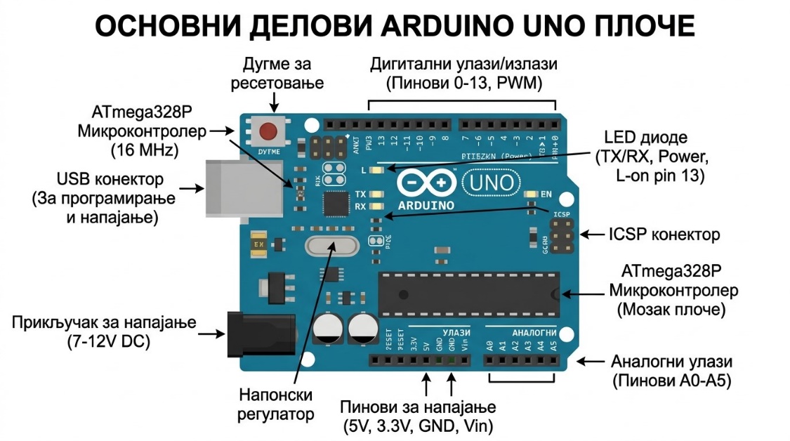
Parts they must find with a finger
- USB — power and upload
- Digital 0–13, analog A0–A5
- GND, 5V, 3.3V
- Onboard LED on pin 13
- Reset and the ATmega328P
Equipment
| Component | Qty | Purpose |
|---|---|---|
| Arduino Uno | 1 | Controller |
| USB cable | 1 | Power and upload |
| Breadboard | 1 | Solderless wiring |
| LED | 1–2 | Visible output |
| 220Ω resistor | 1–2 | Current limit |
| Jumpers | ~4 | Connections |
| Arduino IDE 2.x | 1 | Sketches |
| Tinkercad / Cirkit Designer | 1 | Simulate first |
Exercise 1 · Blink
No external circuit. Proves board, cable, COM port, and the upload toolchain.
| Line | What to say in class |
|---|---|
const int ledPin = 13; | Name the pin once. Change it later without hunting the whole file. |
setup() | Runs once. Configure pins here, not in loop. |
pinMode(ledPin, OUTPUT); | The pin is a speaker, not a microphone. |
digitalWrite / delay(1000) | HIGH is on. 1000 ms is one second. Change it; watch the world change. |
const int ledPin = 13;

void setup() {
  pinMode(ledPin, OUTPUT);
}

void loop() {
  digitalWrite(ledPin, HIGH);
  delay(1000);
  digitalWrite(ledPin, LOW);
  delay(1000);
}- Tools → Board → Arduino Uno
- Tools → Port → the live COM port
- Upload. Onboard LED blinks once per second.
Exercise 2 · External LED
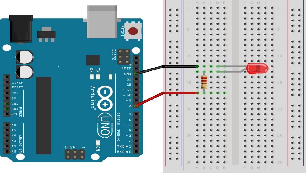
First real circuit. Schematic, photograph, and code must agree. Pin 8 through 220Ω to the LED anode; cathode to GND.
| Uno | Component | Note |
|---|---|---|
| Pin 8 | LED anode (+) | Through 220Ω |
| GND | LED cathode (−) | Direct |
const int ledPin = 8;

void setup() {
  pinMode(ledPin, OUTPUT);
}

void loop() {
  digitalWrite(ledPin, HIGH);
  delay(500);
  digitalWrite(ledPin, LOW);
  delay(500);
}
Student tasks
Basic Change delay. Explain what the LED is doing in milliseconds.
Intermediate Move the LED to another pin and update the constant.
Advanced Add a button with INPUT_PULLUP.
Challenge Three-LED traffic sequence.
Cross-curriculum
| Subject | Hook |
|---|---|
| Physics | Current, voltage, why the resistor limits current |
| Computer science | setup / loop, digital states, timing |
| Technology | Breadboard as a prototype tool |
| Art | Sequence and rhythm as a designed light object |