

Arduino + Processing
Learn by Example
Basic exercises for high-school students — from the first blinking LED to an automatic irrigation system. Updated edition with learning objectives, vocabulary, 42 new exercises, 36 quiz questions and a full answer key.





How to use this handbook
Each module starts with learning objectives and key vocabulary, then walks you through theory and hands-on labs with complete, tested code. At the end you’ll find the original student tasks, new exercises, a self-check quiz and reflection questions. Solutions are in the answer key at the back — try first, check later!
Exercise levels
Basic — everyone · Intermediate — consolidate the lesson · Advanced — go further · Challenge — open-ended projects.
Exercise types
| Type | What you do |
|---|---|
| Predict | Read code and predict what happens before running it |
| Calculate | Use physics and maths formulas with real numbers |
| Build | Wire a circuit and make it work |
| Code | Write or extend a sketch |
| Debug | Find and fix mistakes in code or circuits |
| Explain | Explain a concept in your own words |
| Design | Plan and carry out your own mini-project or investigation |
Lab safety rules
Contents
- F1First Steps with Arduino6 exercises · 5 quiz questions
- F2Processing — Real-Time Visualization6 exercises · 6 quiz questions
- P1Temperature & Humidity — DHT116 exercises · 5 quiz questions
- P2Light Sensor — Photoresistor (LDR)6 exercises · 5 quiz questions
- P3Sonar — Ultrasonic Sensor HC-SR046 exercises · 5 quiz questions
- P4Arduino Ohm Meter with Processing Display6 exercises · 5 quiz questions
- P5Automatic Irrigation System6 exercises · 5 quiz questions
- AAnswer key
- BTeacher notes & errata
First Steps with Arduino
Make a microcontroller do something real — in under ten minutes.
Meet the Arduino Uno, learn how a breadboard works, upload your first program and wire an external LED. This is the foundation for every project in the Digital Challenge series.
- Identify the main parts of the Arduino Uno board (USB, digital pins, analog pins, GND, 5V, reset button, ATmega328P).
- Explain how the rows and rails of a breadboard are connected inside.
- Write, verify and upload a sketch using
setup(),loop(),pinMode(),digitalWrite()anddelay(). - Wire an LED safely with a current-limiting resistor and calculate a suitable resistor value.
- Follow a systematic workflow: schematic → simulation → real wiring → upload → test.
- Microcontroller:
- A tiny computer on a single chip that reads inputs and controls outputs. On the Uno it is the ATmega328P.
- Sketch:
- The name for an Arduino (or Processing) program.
- Digital pin:
- A pin that is either HIGH (5 V) or LOW (0 V). The Uno has pins 0–13.
- Analog pin:
- A pin (A0–A5) that can measure a voltage between 0 and 5 V as a number 0–1023.
- GND (ground):
- The 0 V reference point. Every circuit needs a path back to GND.
- Anode / Cathode:
- The + (longer leg) and − (shorter leg, flat side) of an LED.
- Resistor:
- A component that limits current. Measured in ohms (Ω).
- Breadboard:
- A reusable board for building circuits without soldering.
Required equipment
| Component | Qty | Purpose |
|---|---|---|
| Arduino Uno | 1 | Main development board |
| USB cable | 1 | Connection to computer and program upload |
| Breadboard | 1 | Quick connection without soldering |
| LED diode | 1–3 | Visual indicator of program execution |
| 220 Ω resistor | 1–3 | Current limiting for the LED |
| Push button | 1 | Input for the advanced tasks |
| Jumper wires | ~6 | Connecting components |
| Arduino IDE | 1 | Writing and uploading programs |
| Tinkercad or Circuit Designer | 1 | Circuit simulation and verification |
TheoryWhat is Arduino?
Arduino is a hardware and software platform built around a microcontroller. A small board can read signals from sensors, process them, and then control LEDs, motors, relays, displays or other devices.
Thanks to simple wiring, a huge number of examples and extensive library support, Arduino is ideal for beginners as well as for rapid prototyping in school and project work.
Why the Arduino Uno?
The Uno is the most common first board: stable, well documented and easy to use. It has enough input/output pins for school experiments without unnecessary complexity. Once you know the Uno, moving to a Nano, Mega or ESP32 is easy.
HardwareAnatomy of the Uno
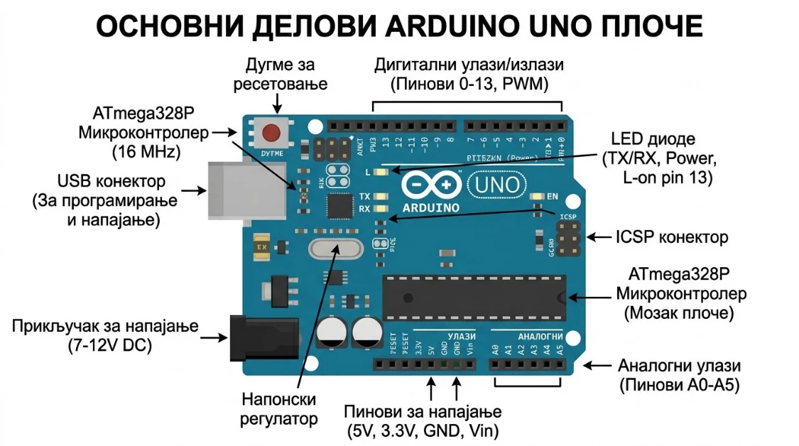
| Part | What it does |
|---|---|
| USB connector | Connects to the computer — power + program upload |
| Digital pins 0–13 | Digital input and output (HIGH / LOW) |
| Analog pins A0–A5 | Read analog sensor values (0–1023) |
| GND | Ground — the negative reference |
| 5V and 3.3V | Power supply pins for components |
| Built-in LED | Connected to pin 13 — perfect for the first test |
| Reset button | Restarts your program from the beginning |
| ATmega328P | The microcontroller chip — the processor of the board |
ElectronicsBreadboard, Resistors & LEDs
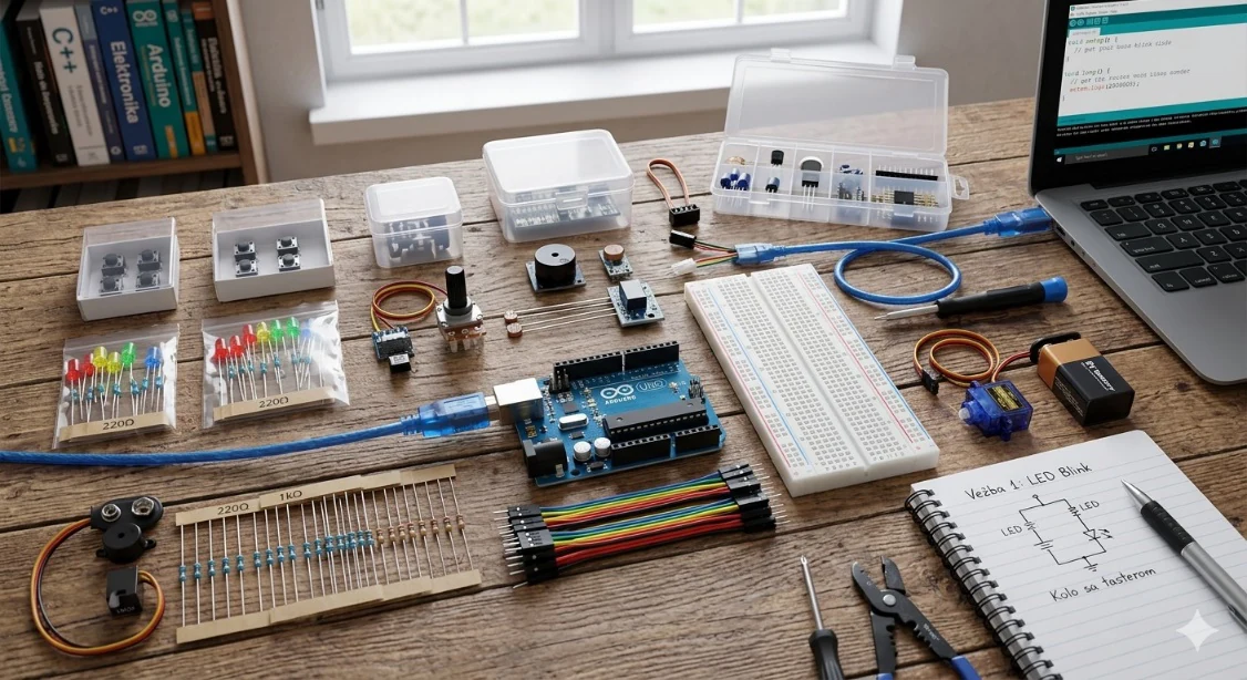
A breadboard lets you connect components without soldering, so you can change connections, test ideas and re-verify circuits quickly. Inside, each short row of 5 holes is connected; the long rails along the edges are usually used for 5V and GND.
A resistor limits current. An LED has almost no resistance of its own, so without a resistor it would draw too much current and burn out — or damage the Arduino pin.
How big should the resistor be?
Use Ohm’s law. The resistor “uses up” the voltage the LED doesn’t need. With a 5 V pin, a red LED that drops about 2 V, and a safe current of about 15 mA:
ToolsArduino IDE, Tinkercad & Circuit Designer
Programs for Arduino are usually written in the Arduino IDE: this is where code is written, checked for errors and uploaded to the board. Tinkercad and Circuit Designer let you plan and simulate a circuit before building it for real.
- ▸writing and editing programs (sketches),
- ▸uploading programs to the Arduino board,
- ▸monitoring program execution via the Serial Monitor,
- ▸adding libraries for sensors and other components.
The IDE is free on the official Arduino website. After installing, select the correct board type and COM port, then upload.
Sensors & actuators you will meet later
| Sensor / Actuator | Type | Used in |
|---|---|---|
| DHT11 | Temperature & humidity sensor | Project 1 |
| LDR (photoresistor) | Light sensor | Project 2 |
| HC-SR04 | Ultrasonic distance sensor | Project 3 |
| SG90 servo motor | Position actuator | Project 3 |
| Relay module | Electrical switch (actuator) | Project 5 |
| Soil moisture sensor | Capacitive sensor | Project 5 |
Hands-onLab 1 — First Upload: Blink
This lab checks that the board is connected, the right COM port is selected and a program uploads successfully. We use the built-in LED on pin 13, so no external circuit is needed — the best possible first test.
const int ledPin = 13;      // built-in LED

void setup() {
  pinMode(ledPin, OUTPUT);  // runs once
}

void loop() {               // repeats forever
  digitalWrite(ledPin, HIGH);
  delay(1000);
  digitalWrite(ledPin, LOW);
  delay(1000);
}| Command | Explanation |
|---|---|
const int ledPin = 13; | Defines the pin number where the LED is connected. |
setup() | Runs once at the start of the program. |
pinMode(ledPin, OUTPUT); | Sets the pin as an output. |
loop() | Repeats indefinitely while the board is powered. |
digitalWrite(ledPin, HIGH/LOW); | Turns the LED on (HIGH = 5 V) or off (LOW = 0 V). |
delay(1000); | Pauses execution for 1000 milliseconds = 1 second. |
How to upload
- 01Open the Arduino IDE.
- 02Go to Tools → Board → Arduino Uno.
- 03Go to Tools → Port and select the correct COM port.
- 04Click Upload (the → arrow icon).
- 05The built-in LED should start blinking once per second.
Hands-onLab 2 — An External LED on a Breadboard
Now move from the built-in LED to an external one and build a real circuit for the first time. Notice how the schematic, the physical wiring and the program connect.
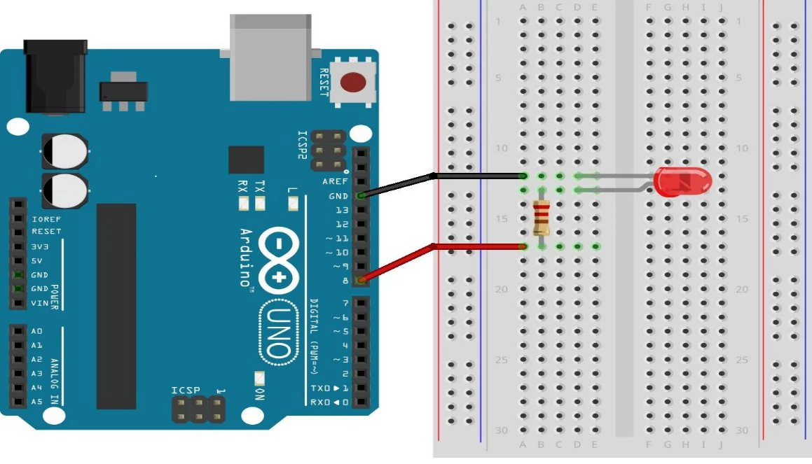
| Arduino Uno | Component | Connection |
|---|---|---|
| Pin 8 | LED anode (+) | Through a 220 Ω resistor |
| GND | LED cathode (−) | Directly to ground |
const int ledPin = 8;

void setup() {
  pinMode(ledPin, OUTPUT);
}

void loop() {
  digitalWrite(ledPin, HIGH);
  delay(500);
  digitalWrite(ledPin, LOW);
  delay(500);
}
The program turns the LED on pin 8 on, waits half a second (500 ms), turns it off, waits again — and repeats forever.
Student tasks
| Level | Task | Goal |
|---|---|---|
| Basic | Change the delay value | Understand the effect of pause duration |
| Intermediate | Move the LED to a different pin | Practise pin assignment in code |
| Advanced | Add a push button to control the LED | Learn INPUT_PULLUP and digitalRead |
| Challenge | Create a 3-LED sequential light effect | Multiple outputs, timing logic |
Troubleshooting
| Problem | Likely cause | Fix |
|---|---|---|
| Upload fails / “port not found” | Wrong COM port or board selected | Tools → Port: pick the port that appears when you plug the board in. |
| LED never lights | LED inserted backwards | Turn the LED around: long leg towards the resistor/pin. |
| LED lights but is very dim | Resistor too large (e.g. 10 kΩ) | Check the colour bands: 220 Ω is red-red-brown. |
| Nothing changes after editing | Code verified but not uploaded | Click Upload, not only Verify. |
F1 · Exercises
Predict the rhythm
Without running it, describe exactly what the LED does with this loop(). How many times does it flash per minute?
void loop() {
  digitalWrite(8, HIGH);
  delay(200);
  digitalWrite(8, LOW);
  delay(800);
}
Hint: Add the two delays to get the length of one full cycle.
Choose the resistor
A blue LED needs about 3.0 V and should run at 10 mA. The Arduino pin gives 5 V. Calculate the ideal resistor, then choose a real value from this list: 100 Ω, 150 Ω, 220 Ω, 330 Ω, 1 kΩ.
Hint: R = (V_supply − V_LED) / I. Remember 10 mA = 0.010 A. Always round up to the next available value.
SOS beacon
Program the external LED to blink SOS in Morse code: three short (200 ms), three long (600 ms), three short — then a 2-second pause. Use a helper function so you don’t repeat yourself.
Hint: Write void flash(int ms) that turns the LED on for ms, then off for 200 ms. Call it inside for loops.
Find three bugs
This sketch should blink an LED on pin 8 but it does not even compile — and even when it compiles, the LED stays dark. Find all three problems.
const int ledPin = 8

void setup() {
  pinMode(ledPin, INPUT);
}

void loop() {
  digitalWrite(ledPin, HIGH);
  delay(500);
  digitalWrite(ledpin, LOW);
  delay(500);
}
Hint: Look for a missing character, a wrong mode, and a spelling difference (C++ is case-sensitive).
Push-button lamp
Add a push button between pin 2 and GND. The LED on pin 8 should be ON only while the button is held down. Use the internal pull-up resistor.
- Place the button across the middle gap of the breadboard.
- Connect one side to pin 2 and the other side to GND.
- In
setup()usepinMode(2, INPUT_PULLUP);. - Remember: with a pull-up, the pin reads LOW when pressed.
Traffic light controller
Build a traffic light with red (pin 10), yellow (pin 9) and green (pin 8) LEDs, each with its own 220 Ω resistor. Sequence: green 4 s → yellow 1 s → red 4 s → red + yellow 1 s → repeat. Extension: add a pedestrian button that shortens the green phase.
Hint: Write a helper void lights(bool r, bool y, bool g, int ms) that sets all three LEDs and then waits.
Self-check quiz
- 1. Which function runs only once when the Arduino starts?
- Aloop()
- Bsetup()
- Cmain()
- Dstart()
- 2. Which leg of an LED connects to GND?
- AThe longer leg (anode)
- BThe shorter leg (cathode)
- CEither — LEDs work both ways
- DNeither — it connects to 5V
- 3. What does
delay(250)do?- AWaits 250 seconds
- BWaits 0.25 seconds
- CBlinks 250 times
- DSets the brightness to 250
- 4. Why do we always put a resistor in series with an LED?
- ATo make it brighter
- BTo limit the current so the LED and pin are not damaged
- CTo change its colour
- DBecause the code needs it
- 5. Which pin is connected to the built-in LED on an Arduino Uno?
- APin 0
- BPin 8
- CPin 13
- DA0
Reflection
- Where in your home or school is there a device that probably contains a microcontroller? What are its inputs and outputs?
- Why is it smart to simulate a circuit before building it?
- What was the hardest part of today — the wiring or the code? Why?
You took the first step with the Arduino platform. Through Blink and the external LED you saw how a program, electronic components and a physical circuit come together as one system. Reading a schematic, writing setup() and loop(), using digitalWrite() and delay() and wiring a breadboard are skills you will use in every following project — from temperature sensors to sonar and automatic irrigation.
Processing — Real-Time Visualization
Turn raw sensor numbers into live graphics on your screen.
Processing is the visual front-end for every project: it receives data from Arduino over USB and draws it as text, bars, colours and animations. Learn the sketch structure, the drawing API, map() and the serial pattern used everywhere.
- Describe how Arduino and Processing communicate over a serial (USB) connection at the same baud rate.
- Write active Processing sketches using
setup()anddraw(), shapes, colours and text. - Use the coordinate system (origin top-left, Y grows downward) to place elements precisely.
- Scale sensor values to screen sizes with
map()and format numbers withnf(). - Receive, validate and parse single values and comma-separated values (CSV) in
serialEvent(). - Send commands from Processing back to Arduino with mouse clicks and key presses.
- Processing:
- A free, Java-based language and environment for visual and interactive programs, created at the MIT Media Lab in 2001.
- PDE:
- Processing Development Environment — the editor, console and toolbar where you write sketches.
- Serial communication:
- Sending data one bit after another over a wire — here, the USB cable between Arduino and computer.
- Baud rate:
- Speed of serial communication in bits per second (e.g. 9600). Both sides must match.
- COM port:
- The name your computer gives the Arduino’s serial connection (e.g. COM3 or /dev/ttyUSB0).
- CSV:
- Comma-Separated Values, e.g.
23.5,61.0— several numbers in one line of text. - Parsing:
- Turning text (a String) into usable data (numbers).
- Frame:
- One execution of
draw(). Processing draws ~60 frames per second.
Required equipment
| Component | Qty | Purpose |
|---|---|---|
| Processing IDE 4.x | 1 | Writing and running visualizations — processing.org |
| Arduino IDE 2.x | 1 | Programming the Arduino board — arduino.cc |
| Arduino Uno | 1 | Sending sensor data over serial |
| USB cable | 1 | Connecting Arduino to the computer |
| Any sensor | 1 | DHT11, LDR, HC-SR04 … to generate data |
TheoryWhat is Processing?
Processing is a free, open-source programming environment designed for visual output, animation and interaction. In Arduino projects it is the visual dashboard: it cannot control hardware directly, but it is excellent at receiving data and turning numbers into compelling visuals.
| Feature | Arduino IDE | Processing |
|---|---|---|
| Primary purpose | Control hardware (sensors, motors) | Create visual output (graphics, charts) |
| Runs on | Microcontroller (Arduino board) | Computer (Windows, macOS, Linux) |
| Output | Signals to components | Graphics on screen |
| Data flow | Sends data via Serial | Receives data via Serial |
| Language base | C / C++ | Java (also Python & JavaScript modes) |
| Sketch structure | setup() + loop() | setup() + draw() |
ArchitectureHow Arduino and Processing Work Together
The two programs talk through serial communication over the USB cable. Every project in the series follows the same pipeline:
- 01A sensor reads a physical value (temperature, distance, light …).
- 02Arduino processes the value and sends it with
Serial.println(). - 03Processing receives the text, parses it and converts it to a number.
- 04Processing draws text, bars, colours or shapes on the screen.
Serial.begin(9600) — Processing: new Serial(this, port, 9600).Core conceptsSketch Structure & Events
Every Processing program (a sketch) has two main functions — just like Arduino — plus optional event functions that run when something happens.
| Function | When it runs | Typical use |
|---|---|---|
setup() | Once, at program start | size(), serial setup, initial variables |
draw() | Continuously (~60 fps) | background(), text(), rect(), shapes |
serialEvent() | When new serial data arrives | Read and parse incoming Arduino data |
mousePressed() | When a mouse button is clicked | UI buttons, interactions |
keyPressed() | When a key is pressed | Send commands back to Arduino |
void setup() {
  // Runs ONCE at the start
  // Set window size, initialize serial port
}

void draw() {
  // Runs CONTINUOUSLY — like loop() in Arduino
  // Draw shapes, text, update the display
}
The Serial library
import processing.serial.*;   // 1. Import the library

Serial myPort;                // 2. Declare the serial port object

void setup() {
  size(400, 300);
  printArray(Serial.list());  // 3. List available ports
  // 4. Open the port — index [0] is usually the first available
  myPort = new Serial(this, Serial.list()[0], 9600);
  myPort.bufferUntil('\n');   // 5. Call serialEvent() once per full line
}Serial.list()[0] is the wrong port, look at the list printed by printArray(Serial.list()) in the console and change the index.Graphics APIDrawing, Colour & Coordinates
| Function | Description | Example |
|---|---|---|
size(w, h) | Set window width and height | size(600, 400) |
background(r,g,b) | Fill background with a colour | background(255) — white |
fill(r,g,b) | Set fill colour for shapes | fill(255, 0, 0) — red |
stroke(r,g,b) | Set outline colour | stroke(0) — black |
text(str, x, y) | Draw text at a position | text("Hello", 50, 100) |
textSize(n) | Set font size | textSize(20) |
rect(x, y, w, h) | Draw a rectangle | rect(50, 100, 200, 30) |
ellipse(x, y, w, h) | Draw an ellipse / circle | ellipse(200, 200, 50, 50) |
line(x1,y1,x2,y2) | Draw a line | line(0, 0, 200, 200) |
map(v,lo1,hi1,lo2,hi2) | Scale a value to a new range | map(temp, 0, 100, 0, 300) |
nf(n, d1, d2) | Format a number as text | nf(3.14159, 1, 2) → "3.14" |
Colour in Processing
Processing uses RGB values from 0 to 255. A fourth value (alpha) sets transparency.
One number means greyscale: fill(0) is black, fill(255) is white.
fill(255, 0, 0);      // Red
fill(0, 255, 0);      // Green
fill(0, 0, 255);      // Blue
fill(255, 255, 0);    // Yellow
fill(128, 0, 128);    // Purple
fill(0);              // Black (shorthand)
fill(255);            // White (shorthand)
fill(255, 0, 0, 150); // Semi-transparent red
The coordinate system
The origin (0, 0) is in the upper-left corner. X grows to the right; Y grows downward. In a 320 × 240 window, (319, 239) is the last visible pixel in the lower-right corner.
rect(50, 100, 200, 30) starts 100 pixels from the top — not the bottom. To draw a bar that grows upward, start at height - barHeight.Mathematicsmap() — the Most Important Function
map() rescales a value from one range to another. Sensor values (0–1023) almost never fit your screen directly, so you will use map() in every project.
// Sensor value 0–1023 mapped to bar width 0–300 pixels:
float barWidth = map(sensorValue, 0, 1023, 0, 300);
rect(50, 100, barWidth, 30);

// Temperature 0–50 °C mapped to the red colour component:
float r = map(temperature, 0, 50, 0, 255);
fill(r, 0, 0);map() does not clamp. If the value goes outside the input range, the result goes outside the output range. Wrap it in constrain(x, min, max) when you need limits.ToolsThe Processing Development Environment
The PDE contains a text editor, a compiler and a display window. It has a message area, a text console, tabs for files, a toolbar and menus. Full reference: processing.org/environment.
| Component | Purpose |
|---|---|
| Text editor | Write and edit sketch code |
| Message area | Feedback while saving, exporting and errors |
| Console | Text output from print() and println() |
| Toolbar | ▶ Run (compile + open window) and ■ Stop |
| Tabs | Manage multiple files within one sketch |
| Menus | File, Edit, Sketch, Debug, Tools, Help |
Most-used menu commands
| Menu | Command | What it does |
|---|---|---|
| File | New / Open / Save As… | Create, open, or save a copy of a sketch |
| File | Examples… | Browse built-in example sketches — great for learning |
| File | Export Application… | Create a standalone program from your sketch |
| Edit | Auto Format | Tidy indentation (Ctrl+T) |
| Edit | Comment / Uncomment | Toggle // on the selected lines |
| Sketch | Present | Run full-screen (Esc to exit) |
| Sketch | Tweak | Change numbers and colours live while running |
| Sketch | Import Library… | Add import lines or install new libraries |
| Sketch | Add File… | Copy images/fonts into the sketch’s data/ folder |
| Debug | Enable Debugger | Breakpoints, Step, Step Into, Step Out |
| Tools | Color Selector… | Pick colours and copy RGB/HSB/Hex values |
| Tools | Archive Sketch | Save a .zip copy of the sketch |
Sketches and the Sketchbook
Each sketch lives in its own folder; the main file has the same name as the folder with a .pde extension. Images, fonts and sounds go into a data/ sub-folder. Find the Sketchbook location in File → Preferences.
MyProject/              ← sketch folder
├── MyProject.pde       ← main file (same name as folder)
└── data/               ← images, fonts, sounds
Renderers
| Renderer | Description | Best for |
|---|---|---|
| Default | Standard 2D renderer | Most 2D sketches and sensor displays |
P2D | Faster OpenGL 2D | High-speed 2D graphics |
P3D | 3D with camera, lighting, materials | 3D visualizations |
FX2D | High-quality JavaFX 2D | Large / high-resolution displays |
Choose a renderer as the third argument of size(), e.g. size(400, 300, P3D);.
Static vs. active sketches
Static — no setup()/draw(); runs once. Good for learning coordinates, shapes and colour.
size(200, 200);
background(255);
noStroke();
fill(255, 204, 0);
rect(30, 20, 50, 50);
Active — uses setup() + draw() for animation, sensors and interaction.
void setup() {
  size(200, 200);
  noStroke();
  fill(0, 102, 153, 204);
}
void draw() {
  background(255);
  rect(width - mouseX, height - mouseY, 50, 50);
  rect(mouseX, mouseY, 50, 50);
}import processing.serial.*;.Hands-on · no hardwareLab 1 — Your First Processing Sketch
Before connecting Arduino, get comfortable with the environment: draw a rounded rectangle, some text, and a circle whose colour changes over time.
float t = 0;

void setup() {
  size(500, 300);
  textAlign(CENTER, CENTER);
}

void draw() {
  background(30);                 // dark grey background
  t++;

  // Animated colour using sine waves
  float r = 127 + 127 * sin(t * 0.05);
  float g = 127 + 127 * sin(t * 0.03);

  // Rounded rectangle (last argument = corner radius)
  fill(r, g, 100);
  rect(50, 80, 400, 60, 10);

  // White text centred in the rectangle
  fill(255);
  textSize(22);
  text("Processing + Arduino = Power!", 250, 110);

  // Animated circle
  fill(r, 50, 200);
  ellipse(250, 220, 60, 60);
}t instead of redeclaring Processing’s built-in frameCount.| Concept | Where in the code |
|---|---|
| Window size | size(500, 300) in setup() |
| Continuous animation | draw() runs ~60 times per second |
| Dynamic colour using maths | sin() of a growing number |
| Rectangle | rect(x, y, width, height, radius) |
| Text | text(), textSize(), textAlign() |
| Circle | ellipse(cx, cy, width, height) |
Hands-onLab 2 — Receiving Data from Arduino
Arduino sends a counter (0–100) every 500 ms; Processing shows it as text and as a bar.
int counter = 0;

void setup() {
  Serial.begin(9600);
}

void loop() {
  Serial.println(counter);   // send number to Processing
  counter++;
  if (counter > 100) counter = 0;
  delay(500);
}import processing.serial.*;
Serial myPort;
int receivedValue = 0;
void setup() {
size(400, 250);
printArray(Serial.list()); // check available ports
myPort = new Serial(this, Serial.list()[0], 9600);
myPort.bufferUntil('\n');
}
void draw() {
background(240);
fill(50);
textSize(20);
text("Received from Arduino: " + receivedValue, 50, 80);
fill(100, 150, 255);
float barW = map(receivedValue, 0, 100, 0, 300);
rect(50, 120, barW, 40);
fill(0);
textSize(16);
text(receivedValue + " / 100", 50 + barW/2, 145);
}
void serialEvent(Serial p) {
String incoming = p.readStringUntil('\n');
if (incoming != null) {
incoming = trim(incoming);
if (incoming.matches("\\d+")) { // only digits? then it is safe
receivedValue = int(incoming);
}
}
}| Part | Explanation |
|---|---|
import processing.serial.* | Imports the serial communication library |
Serial myPort | Object that represents the serial port connection |
Serial.list()[0] | Selects the first available COM port |
serialEvent(Serial p) | Called automatically when new data arrives |
readStringUntil('\n') | Reads one line of text up to the newline |
trim() | Removes spaces and newline characters |
matches("\\d+") | True only if the text contains digits only (safe parsing) |
map(value, 0, 100, 0, 300) | Scales 0–100 to a pixel width of 0–300 |
Hands-onLab 3 — Parsing Multiple Values (CSV)
In Projects 1, 3 and 5 Arduino sends several values in one line, separated by commas. This is the pattern you’ll reuse again and again.
void setup() {
  Serial.begin(9600);
}

void loop() {
  float temperature = 23.5;   // in the real project: a sensor reading
  float humidity    = 61.0;

  Serial.print(temperature);
  Serial.print(",");          // comma separator
  Serial.println(humidity);   // newline at the end
  delay(1000);
}import processing.serial.*;
Serial myPort;
float temperature = 0;
float humidity = 0;
void setup() {
size(500, 300);
myPort = new Serial(this, Serial.list()[0], 9600);
myPort.bufferUntil('\n');
}
void draw() {
background(255);
fill(0);
textSize(22);
text("Temperature: " + nf(temperature, 1, 1) + " \u00B0C", 50, 100);
text("Humidity: " + nf(humidity, 1, 1) + " %", 50, 150);
fill(220, 50, 50); // temperature bar
rect(50, 170, map(temperature, 0, 50, 0, 380), 25);
fill(50, 100, 220); // humidity bar
rect(50, 210, map(humidity, 0, 100, 0, 380), 25);
}
void serialEvent(Serial p) {
String data = p.readStringUntil('\n');
if (data != null && data.contains(",")) {
String[] values = split(trim(data), ",");
if (values.length == 2) {
temperature = float(values[0]);
humidity = float(values[1]);
}
}
}| Step | Code | Why |
|---|---|---|
| 1. Read line | readStringUntil('\n') | Wait for a complete line |
| 2. Check not null | if (data != null) | Avoid errors on empty reads |
| 3. Check format | data.contains(",") | Confirm it is CSV |
| 4. Split | split(trim(data), ",") | Divide into an array at each comma |
| 5. Check length | values.length == 2 | Ensure the right number of values |
| 6. Convert | float(values[0]) | Turn text into a number |
Hands-onLab 4 — Sending Commands Back to Arduino
Communication works both ways. Processing can send a character to switch a pump (Project 5) or start a servo (Project 3). Here, mouse clicks and keys switch the built-in LED.
void setup() {
  Serial.begin(9600);
  pinMode(13, OUTPUT);              // built-in LED
}

void loop() {
  if (Serial.available() > 0) {
    char cmd = Serial.read();
    if (cmd == '1')      digitalWrite(13, HIGH);  // LED ON
    else if (cmd == '0') digitalWrite(13, LOW);   // LED OFF
  }
}import processing.serial.*;
Serial myPort;
boolean ledOn = false;
void setup() {
size(400, 220);
myPort = new Serial(this, Serial.list()[0], 9600);
textAlign(CENTER, CENTER);
}
void draw() {
background(240);
fill(30);
textSize(18);
text("Arduino LED Control", 200, 30);
text("Click buttons or press 1 / 0 on keyboard", 200, 60);
fill(ledOn ? color(0, 200, 0) : color(180)); // ON button
rect(60, 100, 120, 50, 8);
fill(255);
text("ON", 120, 125);
fill(!ledOn ? color(200, 50, 50) : color(180)); // OFF button
rect(220, 100, 120, 50, 8);
fill(255);
text("OFF", 280, 125);
fill(30);
textSize(16);
text("Status: LED is " + (ledOn ? "ON" : "OFF"), 200, 190);
}
void setLed(boolean on) {
myPort.write(on ? '1' : '0');
ledOn = on;
}
void mousePressed() {
if (mouseX > 60 && mouseX < 180 && mouseY > 100 && mouseY < 150) setLed(true);
if (mouseX > 220 && mouseX < 340 && mouseY > 100 && mouseY < 150) setLed(false);
}
void keyPressed() {
if (key == '1') setLed(true);
if (key == '0') setLed(false);
}| Project | Sensor | Visualization | Key technique |
|---|---|---|---|
| 1 — DHT11 | Temperature & humidity | Two-value text + bars | CSV parsing, 2 values |
| 2 — LDR | Light intensity | Single bar + colour change | map(), background colour |
| 3 — HC-SR04 | Distance (sonar) | Radar sweep display | Trigonometry, ellipse, line |
| 4 — Ohm meter | Resistance | Numeric display + gauge | nf(), arc(), text |
| 5 — Irrigation | Soil moisture | Status display + bar | Threshold logic, fill colour |
Cheat sheetArduino vs. Processing — Quick Reference
| Concept | Arduino IDE | Processing |
|---|---|---|
| Program entry point | setup() + loop() | setup() + draw() |
| Print to console | Serial.println() | println() |
| Read input | Serial.read() | myPort.readStringUntil() |
| Delay / pause | delay(ms) | delay(ms) — avoid in draw() |
| Variable types | int, float, char, bool | int, float, String, boolean |
| Draw rectangle / text | — (no screen) | rect(), text() |
| Colour | — (no screen) | fill(), stroke() |
| Event handling | — | mousePressed(), keyPressed() |
| Import library | #include <Lib.h> | import library.*; |
Student tasks
| Level | Task | Goal |
|---|---|---|
| Basic | Display a single number from Arduino as text | Serial, int(), text() |
| Intermediate | Draw a coloured bar proportional to the sensor value | map(), rect(), fill() |
| Advanced | Parse two values (CSV) and display both with bars | split(), multiple visual elements |
| Challenge | Add ON/OFF buttons that send commands to Arduino | mousePressed(), Serial.write() |
| Challenge | Create a real-time graph of the last 100 readings | Arrays, shifting values, line() |
Troubleshooting
| Problem | Likely cause | Fix |
|---|---|---|
| Port not found / empty Serial.list() | Arduino not connected or driver missing | Check USB; install the CH340 driver for clone boards. |
| Port busy / in use | Arduino Serial Monitor still open | Close the Serial Monitor in the Arduino IDE first. |
| No data received | Wrong index in Serial.list()[0] | Run printArray(Serial.list()) and choose the right index. |
| Garbage characters | Baud rate mismatch | Use 9600 on both sides. |
| NullPointerException | data is null (incomplete line) | Always check if (data != null). |
| Wrong / garbage values on screen | Parsing non-numeric text | Validate with data.matches("\\d+") or check length after split(). |
| Sketch freezes | Heavy work or delay() inside draw() | Read serial in serialEvent(); never block draw(). |
F2 · Exercises
map() by hand
Calculate each result without a computer, then check with the playground above.
a) map(512, 0, 1023, 0, 300)
b) map(25, 0, 50, 0, 255)
c) map(750, 1023, 300, 0, 100)
Hint: result = lo2 + (value − lo1) × (hi2 − lo2) / (hi1 − lo1). In (c) the input range is reversed — that’s fine.
Where will it appear?
In a size(400, 300) window, describe where each shape appears: ellipse(200, 150, 40, 40), rect(0, 280, 400, 20), ellipse(width, 0, 60, 60).
Bouncing ball
No hardware: make a ball move across the window and bounce off all four walls. Change its colour every time it hits a wall.
Hint: Store position (x, y) and speed (dx, dy). Each frame add the speed. If x < 0 or x > width, flip the sign of dx.
Why is the screen blank?
Arduino is sending numbers, but this sketch shows nothing and sometimes crashes with a NullPointerException. Find the problems.
import processing.serial.*;
Serial myPort;
int value;

void setup() {
  size(400, 200);
  myPort = new Serial(this, Serial.list()[0], 115200);
}

void draw() {
  fill(0);
  text(value, 50, 100);
}

void serialEvent(Serial p) {
  value = int(trim(p.readStringUntil('\n')));
}
Hint: Compare with Lab 2: what speed does Arduino use? What happens to old text when there is no background()? What if the line is not complete yet?
Real-time line graph
Extend Lab 2: keep the last 100 received values in an array and draw them as a scrolling line graph across the window.
Hint: Shift every element one place left (vals[i] = vals[i+1]) and put the new value at the end. Use map() for both X (index → width) and Y (value → height, reversed!).
Three-value protocol
Design your own message format for three values (e.g. x,y,button from a joystick). Write the Arduino side with fake values from random(), and a Processing sketch that moves a circle with x/y and changes its colour when button = 1. Your parser must ignore malformed lines.
Hint: Check values.length == 3 and wrap each conversion. Test robustness by sending a broken line such as 12,, or hello.
Self-check quiz
- 1. What is the Processing equivalent of Arduino’s loop()?
- Asetup()
- Bdraw()
- CserialEvent()
- Drepeat()
- 2. In Processing, where is the point (0, 0)?
- ACentre of the window
- BBottom-left corner
- CTop-left corner
- DBottom-right corner
- 3. Arduino uses Serial.begin(9600). What must Processing use?
- Anew Serial(this, port, 115200)
- Bnew Serial(this, port, 9600)
- CAny speed works
- DSerial.begin(9600)
- 4. What does map(50, 0, 100, 0, 400) return?
- A50
- B100
- C200
- D400
- 5. Arduino sends "24.5,60". What does split(trim(data), ",") give?
- AA single number 84.5
- BAn array ["24.5", "60"]
- CThe text "24.560"
- DAn error
- 6. Why must the Serial Monitor be closed before running Processing?
- AIt slows the computer down
- BOnly one program can open a serial port at a time
- CIt changes the baud rate
- DIt resets the Arduino
Reflection
- Explain the full journey of one sensor reading — from the physical world to a pixel on your screen — in your own words.
- Why is it a good idea to validate incoming data before using it?
- Where have you seen live data visualizations in everyday life (weather apps, fitness trackers, …)?
Processing is the visual bridge between the physical world and the screen. Once you understand how data flows from a sensor through Arduino’s serial port into Processing’s draw(), you can build any real-time visualization you can imagine. Serial setup, parsing, drawing with map(), and sending commands back to Arduino are a complete toolkit for every project that follows.
Temperature & Humidity — DHT11
Build a mini weather station that streams live climate data.
Measure air temperature and relative humidity with a DHT11 sensor, send both values as CSV over serial, and visualize them in real time with Processing — your first IoT-style system.
- Install and use an Arduino library (Adafruit DHT sensor library).
- Wire a digital sensor and explain the role of a pull-up resistor.
- Explain what relative humidity means physically.
- Send two measurements in one CSV line and parse them in Processing.
- Detect sensor errors with
isnan()and add a high-temperature alarm.
- DHT11:
- A low-cost digital sensor for temperature (0–50 °C, ±2 °C) and humidity (20–90 % RH, ±5 %).
- Relative humidity (RH):
- How much water vapour the air holds compared with the maximum it could hold at that temperature, in %.
- Library:
- Ready-made code you include to talk to a component without writing everything yourself.
- Pull-up resistor:
- A resistor that keeps a signal line at HIGH when nothing is pulling it LOW.
- NaN:
- “Not a Number” — the value returned when a reading failed. Test with
isnan(). - IoT:
- Internet of Things — everyday objects with sensors that share data.
Required equipment
| Component | Qty | Purpose |
|---|---|---|
| Arduino Uno | 1 | Microcontroller |
| DHT11 sensor | 1 | Temperature and humidity measurement |
| 10 kΩ resistor | 1 | Pull-up resistor (only for the bare 3/4-pin sensor) |
| Breadboard | 1 | Component connection |
| Jumper wires | ~5 | Component connection |
| USB cable | 1 | Connection to computer |
| Arduino IDE + Processing | 1 | Programming and visualization |
TheoryTheoretical Background
What is the DHT11?
The DHT11 is a digital sensor: it measures temperature and relative humidity and sends the result as a digital signal. No analog-to-digital conversion is needed, it is easy to connect, and ready-made libraries exist — perfect for beginners.
What is relative humidity?
Relative humidity is the percentage of water vapour in the air compared with the maximum amount the air can hold at that temperature and normal pressure. Warm air can hold more water than cold air — that’s why a cold bottle from the fridge “sweats” on a warm day.
Serial communication
Arduino sends both readings in one line, separated by a comma:
Serial.println("24.5,60"); // temperature = 24.5 °C, humidity = 60 %Hands-onExercise 1 — Connecting the DHT11
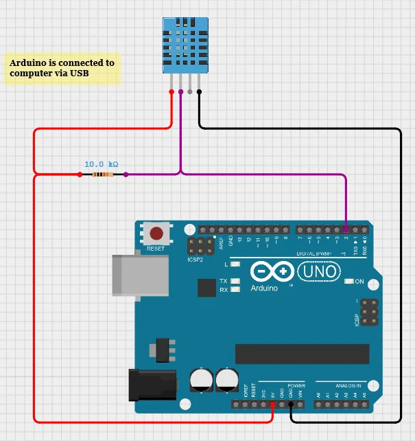
| DHT11 pin | Arduino pin |
|---|---|
| VCC | 5V |
| GND | GND |
| DATA | Digital pin 2 |
Using the bare 3/4-pin sensor? Place a 10 kΩ resistor between VCC and DATA.
Step 1 — Install the library
- 01In the Arduino IDE open Sketch → Include Library → Manage Libraries.
- 02Search for “DHT sensor library” by Adafruit.
- 03Click Install (accept the “Adafruit Unified Sensor” dependency).
Step 2 — Arduino code
#include "DHT.h"

#define DHTPIN 2
#define DHTTYPE DHT11

DHT dht(DHTPIN, DHTTYPE);

void setup() {
  Serial.begin(9600);
  dht.begin();
}

void loop() {
  float humidity = dht.readHumidity();
  float temperature = dht.readTemperature();   // Celsius

  if (isnan(humidity) || isnan(temperature)) {
    Serial.println("Failed to read from DHT sensor!");
    delay(2000);
    return;
  }

  Serial.print(temperature);
  Serial.print(",");
  Serial.println(humidity);
  delay(2000);                                 // DHT11: max. 1 reading per second
}| Command | Explanation |
|---|---|
dht.readTemperature() | Reads the temperature in °C |
dht.readHumidity() | Reads the relative humidity in % |
isnan(x) | True if the reading failed (Not a Number) |
Serial.print() | Sends data to the computer |
delay(2000) | Waits 2 seconds between readings |
Hands-onExercise 2 — Data Visualization in Processing
The sketch reads the data from Arduino, shows temperature and humidity as text, and visualizes both with bars.
import processing.serial.*;

Serial myPort;
float temp = 0, hum = 0;

void setup() {
  size(500, 260);
  myPort = new Serial(this, Serial.list()[0], 9600);
  myPort.bufferUntil('\n');
}

void draw() {
  background(255);
  fill(0);
  textSize(20);
  text("Temperature: " + nf(temp, 1, 1) + " \u00B0C", 50, 70);
  text("Humidity: " + nf(hum, 1, 1) + " %", 50, 150);

  fill(220, 50, 50);                                  // temperature bar 0–50 °C
  rect(50, 85, map(temp, 0, 50, 0, 400), 25);
  fill(50, 100, 220);                                 // humidity bar 0–100 %
  rect(50, 165, map(hum, 0, 100, 0, 400), 25);

  if (temp > 30) {                                    // alert system
    fill(255, 0, 0);
    text("WARNING: HIGH TEMPERATURE!", 50, 235);
  }
}

void serialEvent(Serial p) {
  String data = p.readStringUntil('\n');
  if (data != null && data.contains(",")) {
    String[] values = split(trim(data), ",");
    if (values.length == 2) {
      temp = float(values[0]);
      hum  = float(values[1]);
    }
  }
}import processing.serial.*;, moved reading into serialEvent() and added bars and the alarm.Student tasks
| Level | Task | Goal |
|---|---|---|
| Basic | Display temperature and humidity | |
| Intermediate | Add graphical progress bars | |
| Advanced | Add a high-temperature alarm | |
| Challenge | Save data to a CSV file | |
| Challenge | Draw a real-time graph |
Troubleshooting
| Problem | Likely cause | Fix |
|---|---|---|
| No data received | Incorrect COM port | Use printArray(Serial.list()) to find the correct port. |
| “Failed to read” message | Poorly connected sensor or wrong pin | Check DATA → pin 2 and that DHTTYPE is DHT11 (not DHT22). |
| Unstable values | Poor contact on the breadboard | Press wires in firmly; avoid long loose jumpers. |
| Processing not receiving data | Serial speed mismatch | Both sides 9600 baud. |
P1 · Exercises
Read the datasheet
The DHT11 datasheet says: range 0–50 °C, accuracy ±2 °C; humidity 20–90 % RH, accuracy ±5 %. Your sensor shows 22 °C and 48 %. What are the possible real values? Could you use this sensor in a freezer?
Parse it in your head
For each line Arduino might send, write what temp and hum become in the Processing sketch (or “unchanged”): 25.0,40.0 · Failed to read from DHT sensor! · 26.1, · 27.3,55.0,1
Hint: Check each guard: contains(",") and values.length == 2.
Comfort zone indicator
Classrooms are comfortable between 20–24 °C and 40–60 % RH. Add a large circle to the Processing sketch that is green inside the comfort zone, yellow if only one value is outside, and red if both are outside. Write the status text next to it.
Dew point estimate
A simple approximation for the dew point (the temperature at which water condenses) is Td ≈ T − (100 − RH) / 5. Calculate Td for (a) 25 °C / 60 % and (b) 18 °C / 90 %. Then add the calculation to Processing and display it.
Log to a CSV file
Save every reading with a timestamp to weather.csv so you can open it later in a spreadsheet and draw a chart.
Hint: Use PrintWriter output = createWriter("weather.csv"); in setup(), output.println(...) in serialEvent(), and output.flush(); output.close(); when a key is pressed.
Classroom climate study
Run a real investigation: log the classroom climate for one full lesson with windows closed and one with windows open. Plot both datasets, compare the averages, and write a short recommendation for your school (how often should you ventilate?).
- Formulate a hypothesis.
- Collect data with your logger (P1.5).
- Compute min, max and average for each condition.
- Present a chart and a 5-sentence conclusion.
Self-check quiz
- 1. What does the DHT11 measure?
- ALight and sound
- BTemperature and relative humidity
- CDistance and speed
- DAir pressure
- 2. What does isnan(temperature) check?
- AWhether the temperature is negative
- BWhether the reading failed (Not a Number)
- CWhether it is too hot
- DWhether the sensor is DHT22
- 3. Why does the code wait 2 seconds between readings?
- ATo save battery
- BThe DHT11 can only give a new reading about once per second
- CProcessing is slow
- DTo make the LED blink
- 4. Warm air can hold … water vapour than cold air.
- Aless
- Bthe same amount of
- Cmore
- Dno
- 5. The 4-pin bare DHT11 needs a 10 kΩ resistor between…
- ADATA and GND
- BVCC and DATA
- CVCC and GND
- DNothing — it never needs one
Reflection
- Where would you place the sensor in a room to get a fair measurement? Why not next to the radiator or window?
- Our sensor is ±2 °C accurate. Is that good enough for a weather station? For a hospital incubator?
- How could this project help save energy at school?
This project introduced working with digital sensors, libraries, and two-value data streams. By combining the Arduino Uno with Processing you built a real-time climate monitor — the same principle used in smart homes, greenhouses and weather stations around the world.
Light Sensor — Photoresistor (LDR)
Read the brightness of the room and paint it on screen.
Use a photoresistor in a voltage divider, read it with analogRead() (0–1023), and build a Processing display whose bar and background react to light in real time.
- Explain how the resistance of an LDR changes with light.
- Build a voltage divider and calculate its output voltage.
- Convert between voltage and the 10-bit ADC value (0–1023).
- Visualize a single sensor value as text, a bar and a background colour.
- Calibrate a sensor by measuring its minimum and maximum in real conditions.
- LDR / photoresistor:
- A resistor whose resistance falls when light shines on it (≈ 1 MΩ in darkness, ≈ 1 kΩ in bright light).
- Voltage divider:
- Two resistors in series; the voltage in the middle depends on their ratio.
- ADC:
- Analog-to-Digital Converter: turns 0–5 V into a number 0–1023 (10-bit) on the Uno.
- analogRead():
- Arduino function that reads an analog pin and returns 0–1023.
- Calibration:
- Measuring real minimum and maximum values so your scale fits reality.
Required equipment
| Component | Qty | Purpose |
|---|---|---|
| Arduino Uno | 1 | Microcontroller |
| Photoresistor (LDR) | 1 | Light sensing |
| 10 kΩ resistor | 1 | Voltage divider |
| Breadboard | 1 | Component connection |
| Jumper wires | ~5 | Component connection |
| USB cable | 1 | Connection to computer |
| Processing IDE | 1 | Data visualization |
TheoryTheoretical Background
How does a photoresistor work?
An LDR (Light Dependent Resistor) is made of a semiconductor. Light gives its electrons enough energy to conduct, so in bright light the resistance decreases; in darkness it increases.
The voltage divider
Arduino can’t measure resistance directly — only voltage. So we put the LDR in series with a fixed 10 kΩ resistor. The voltage at the junction (connected to A0) changes with light.
Hands-onExercise 1 — Circuit Setup & Arduino Code
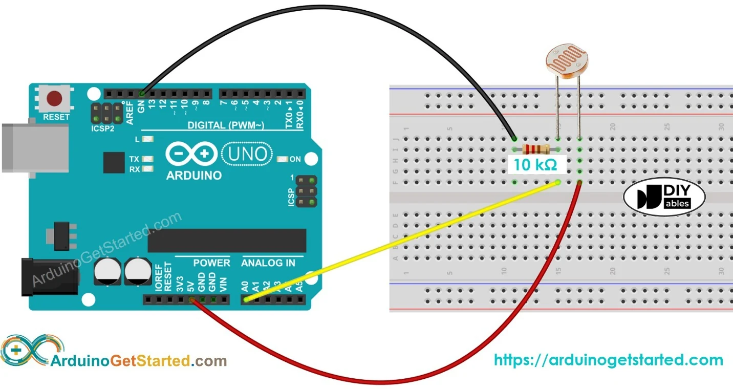
| Component | Connects to |
|---|---|
| LDR (leg 1) | 5V |
| LDR (leg 2) | A0 and 10 kΩ resistor (leg 1) |
| 10 kΩ resistor (leg 2) | GND |
const int sensorPin = A0;

void setup() {
  Serial.begin(9600);
}

void loop() {
  int lightValue = analogRead(sensorPin);   // 0 (dark) … 1023 (bright)
  Serial.println(lightValue);
  delay(200);
}Hands-onExercise 2 — Processing Visualization
Start simple with a text display, then upgrade to the robust serialEvent() version with a bar.
import processing.serial.*;

Serial myPort;
int lightLevel = 0;

void setup() {
  size(400, 200);
  myPort = new Serial(this, Serial.list()[0], 9600);
}

void draw() {
  background(255);
  fill(0);
  textSize(20);
  text("Light Intensity: " + lightLevel, 50, 100);

  if (myPort.available() > 0) {
    String val = myPort.readStringUntil('\n');
    if (val != null) lightLevel = int(trim(val));
  }
}import processing.serial.*;
Serial myPort;
int lightLevel = 0;
void setup() {
size(400, 200);
myPort = new Serial(this, Serial.list()[0], 9600);
myPort.bufferUntil('\n');
}
void draw() {
background(255);
fill(0);
textSize(20);
text("Light Intensity: " + lightLevel, 50, 50);
fill(0, 100, 255);
rect(50, 100, map(lightLevel, 0, 1023, 0, 300), 30);
}
void serialEvent(Serial p) {
String val = p.readStringUntil('\n');
if (val != null) {
val = trim(val);
if (val.matches("\\d+")) lightLevel = int(val);
}
}background(255) with background(map(lightLevel, 0, 1023, 0, 255)); — the window now gets darker when the room gets darker.Student tasks
| Level | Task | Goal |
|---|---|---|
| Basic | Display the numeric light value | |
| Intermediate | Draw a coloured bar proportional to the light level | |
| Advanced | Change the background colour based on light intensity | |
| Challenge | Log values with timestamps to a text file |
Troubleshooting
| Problem | Likely cause | Fix |
|---|---|---|
| Value stays at 0 | LDR not connected or open circuit | Check the LDR leg goes to 5V and the junction to A0. |
| Value stays at 1023 | Resistor missing or GND not connected | Check the 10 kΩ resistor goes from A0 to GND. |
| Unstable readings | Poor breadboard contact or flickering lights | Press components in firmly; average several readings. |
| Range is small (e.g. 400–700) | Fixed resistor doesn’t match the LDR | Try 4.7 kΩ or 22 kΩ, or calibrate with map(). |
P2 · Exercises
Voltage divider practice
With R_fixed = 10 kΩ and 5 V supply, calculate V_A0 and the expected analogRead() value when the LDR is (a) 1 kΩ (bright), (b) 10 kΩ (normal room), (c) 100 kΩ (dark).
Hint: V_A0 = 5 × 10 / (R_LDR + 10) with resistances in kΩ; reading = V_A0 / 5 × 10²³.
Swap the parts
What happens to the readings if you swap the LDR and the 10 kΩ resistor (LDR now between A0 and GND)?
Automatic night-light
Add an LED (pin 9 + 220 Ω). Turn it on when the reading drops below a threshold of your choice and off when it is brighter. Print the state to the Serial Monitor.
Smooth dimming with PWM
Instead of on/off, make the LED on pin 9 get brighter as the room gets darker, using analogWrite() (0–255).
Hint: Pin 9 supports PWM (~). Use map(light, 0, 1023, 255, 0) — note the reversed output range.
Calibrate with min/max
Your sensor never reaches 0 or 1023. Make Processing remember the smallest and largest values it has seen and map the bar between those, so it always uses the full width. Press R to reset calibration.
Sunrise logger
Design an experiment that measures how light levels change near a window during a whole school day. Log a value every minute with a timestamp, then plot a graph. At what time is your classroom brightest? Does it depend on the weather?
Self-check quiz
- 1. In bright light, an LDR’s resistance…
- Aincreases
- Bdecreases
- Cstays the same
- Dbecomes zero
- 2. What range does analogRead() return on the Arduino Uno?
- A0–255
- B0–1023
- C0–5
- D−512–512
- 3. Why do we need the fixed 10 kΩ resistor?
- ATo protect the LDR from light
- BTo form a voltage divider so Arduino can measure a changing voltage
- CTo make the LED brighter
- DIt is optional
- 4. An analog reading of 512 corresponds to roughly…
- A0.5 V
- B1 V
- C2.5 V
- D5 V
- 5. The reading is always 1023. The most likely cause is:
- AToo much light
- BFixed resistor or GND not connected
- CWrong baud rate
- DThe LDR is reversed
Reflection
- Which devices you own adjust themselves to light? How do you think they do it?
- The LDR response is not linear. Why might that matter when you build a “lux meter”?
- How could automatic lighting reduce your school’s energy use?
You learned how analog sensors and voltage dividers work, and how to turn a changing resistance into a live visualization. By combining the Arduino Uno with Processing you built an interactive light meter — the same idea behind auto-brightness screens and smart street lighting.
Sonar — Ultrasonic Sensor HC-SR04
Measure distance with sound and build a working radar screen.
Use the HC-SR04 to measure distance with ultrasound, control an SG90 servo from Processing, make the servo react to obstacles, and finally combine everything into a sweeping radar display.
- Explain how an ultrasonic sensor measures distance using the echo time.
- Calculate distance from time with d = v·t / 2 and explain the factor 2.
- Control a servo motor with the Servo library and commands from Processing.
- Write non-blocking code so Arduino can react to new commands at any time.
- Convert polar coordinates (angle, distance) to screen coordinates with sin() and cos().
- Ultrasound:
- Sound above human hearing (> 20 kHz). The HC-SR04 uses 40 kHz.
- Echo:
- A reflected sound wave that returns to the sensor.
- pulseIn():
- Arduino function that measures how long a pin stays HIGH, in microseconds.
- Servo motor:
- A motor that turns to a precise angle (0–180°) controlled by a PWM signal.
- PWM:
- Pulse-Width Modulation — switching a signal on and off quickly; the pulse width carries the information.
- Polar coordinates:
- Describing a point by an angle and a distance from the centre, like a radar does.
Required equipment
| Component | Qty | Purpose |
|---|---|---|
| Arduino Uno | 1 | Microcontroller |
| HC-SR04 ultrasonic sensor | 1 | Distance measurement (2–400 cm) |
| SG90 servo motor | 1 | Radar sweep (Ex. 2–4) |
| Plastic holder for sensor | 1 | Mount the sensor on the servo |
| Breadboard + jumper wires | 1 set | Component connection |
| USB cable | 1 | Connection to computer |
| Processing IDE | 1 | Visualization |
TheoryPhysics of Ultrasonic Sensing
The sensor emits a short burst of ultrasound (~40 kHz). When the wave hits an object it bounces back. The sensor measures the time until the echo returns — just like bats and dolphins do.
Hands-onExercise 1 — Measure Distance & Display in Processing
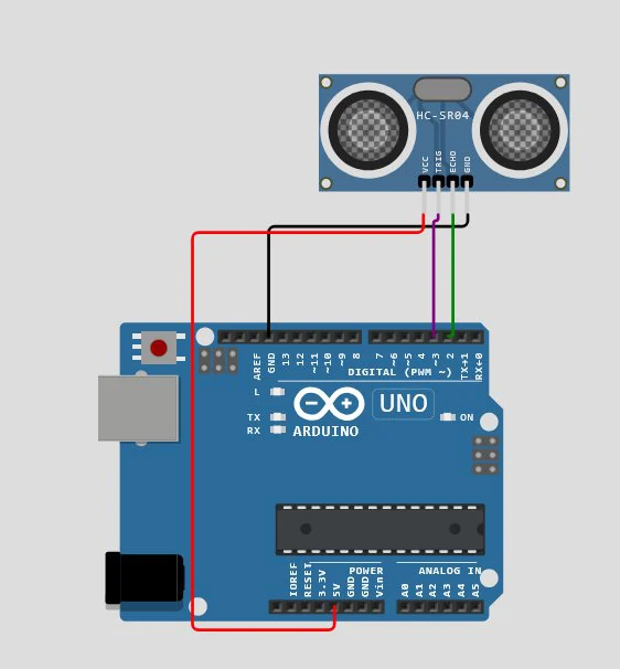
| HC-SR04 pin | Arduino pin |
|---|---|
| VCC | 5V |
| GND | GND |
| TRIG | Pin 3 |
| ECHO | Pin 2 |
#define trigPin 3
#define echoPin 2

void setup() {
  Serial.begin(9600);
  pinMode(trigPin, OUTPUT);
  pinMode(echoPin, INPUT);
}

void loop() {
  digitalWrite(trigPin, LOW);
  delayMicroseconds(2);
  digitalWrite(trigPin, HIGH);          // 10 µs trigger pulse
  delayMicroseconds(10);
  digitalWrite(trigPin, LOW);

  long duration = pulseIn(echoPin, HIGH, 30000);  // timeout 30 ms ≈ 5 m
  float distance = duration * 0.0343 / 2;         // cm
  Serial.println(distance);
  delay(200);
}import processing.serial.*;
Serial myPort;
float distance;
void setup() {
size(600, 200);
printArray(Serial.list());
myPort = new Serial(this, Serial.list()[0], 9600);
myPort.bufferUntil('\n');
}
void draw() {
background(255);
fill(0);
textSize(24);
text("Distance: " + nf(distance, 0, 2) + " cm", 50, 50);
fill(100, 200, 255); // horizontal bar
rect(50, 100, map(constrain(distance, 0, 200), 0, 200, 0, width - 100), 30);
}
void serialEvent(Serial p) {
String data = p.readStringUntil('\n');
if (data != null) distance = float(trim(data));
}Hands-onExercise 2 — Control the SG90 Servo from Processing
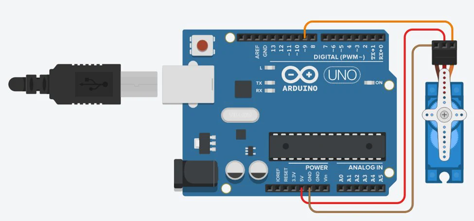
| Servo wire | Arduino pin |
|---|---|
| Signal (orange) | Pin 9 |
| VCC (red) | 5V |
| GND (brown) | GND |
Background reading: The Beginner’s Guide to Micro Servos — docs.arduino.cc/learn/electronics/servo-motors
#include <Servo.h>

Servo servo;
bool sweeping = false;
int angle = 0;
int step = 1;

void setup() {
  Serial.begin(9600);
  servo.attach(9);
}

void loop() {
  if (Serial.available()) {
    String command = Serial.readStringUntil('\n');
    command.trim();
    sweeping = (command == "1");      // "1" = START, anything else = STOP
  }

  if (sweeping) {                     // one small step per loop()
    angle += step;
    if (angle >= 180 || angle <= 0) step = -step;
    servo.write(angle);
    delay(10);
  }
}import processing.serial.*;
Serial myPort;
boolean isSweeping = false;
void setup() {
size(400, 200);
myPort = new Serial(this, Serial.list()[0], 9600);
textAlign(CENTER, CENTER);
}
void draw() {
background(240);
textSize(16);
fill(0);
text("Servo Control", width/2, 30);
drawButton("START", 100, 100, isSweeping);
drawButton("STOP", 250, 100, !isSweeping);
}
void drawButton(String label, int x, int y, boolean active) {
fill(active ? color(0, 200, 0) : color(180));
rect(x, y, 100, 40, 7);
fill(0);
text(label, x + 50, y + 20);
}
void mousePressed() {
if (mouseX > 100 && mouseX < 200 && mouseY > 100 && mouseY < 140) {
myPort.write("1\n");
isSweeping = true;
} else if (mouseX > 250 && mouseX < 350 && mouseY > 100 && mouseY < 140) {
myPort.write("0\n");
isSweeping = false;
}
}- ▸START sends
"1"→ Arduino begins sweeping the servo. - ▸STOP sends
"0"→ Arduino halts the movement immediately. - ▸Expand it with an angle slider, speed control or real-time feedback.
Hands-onExercise 3 — Ultrasonic Sensor Controlling the Servo
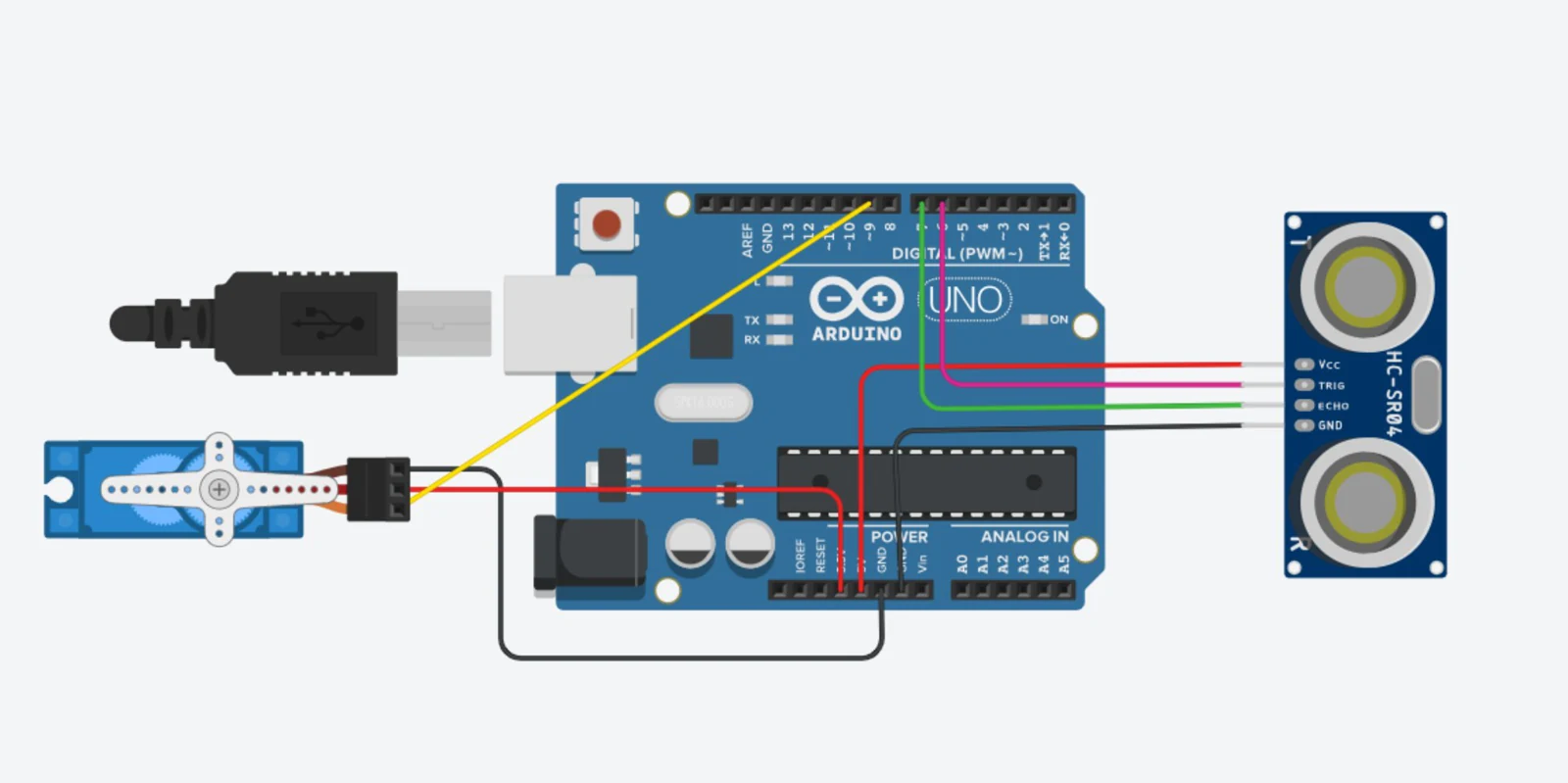
The servo turns to 90° when an object is closer than 50 cm and returns to 0° otherwise — like an automatic barrier.
#include <Servo.h>

const int TRIG_PIN = 6;
const int ECHO_PIN = 7;
const int SERVO_PIN = 9;
const int DISTANCE_THRESHOLD = 50;   // centimetres

Servo servo;
float duration_us, distance_cm;

void setup() {
  Serial.begin(9600);
  pinMode(TRIG_PIN, OUTPUT);
  pinMode(ECHO_PIN, INPUT);
  servo.attach(SERVO_PIN);
  servo.write(0);
}

void loop() {
  digitalWrite(TRIG_PIN, HIGH);      // 10 µs pulse
  delayMicroseconds(10);
  digitalWrite(TRIG_PIN, LOW);

  duration_us = pulseIn(ECHO_PIN, HIGH);
  distance_cm = 0.017 * duration_us; // = 0.0343 / 2

  if (distance_cm < DISTANCE_THRESHOLD) servo.write(90);
  else                                  servo.write(0);

  Serial.print("distance: ");
  Serial.print(distance_cm);
  Serial.println(" cm");
  delay(500);
}text() and (b) as a horizontal bar. Careful: this sketch sends distance: 23.4 cm, not just a number — see exercise P3.4.ProjectExercise 4 — Build a Radar Scanner
The servo sweeps from 0° to 180°; at each step Arduino measures the distance and sends angle,distance. Processing converts each pair to an (x, y) point.
#include <Servo.h>

Servo myServo;
#define trigPin 9
#define echoPin 10

float measure() {
  digitalWrite(trigPin, LOW);
  delayMicroseconds(2);
  digitalWrite(trigPin, HIGH);
  delayMicroseconds(10);
  digitalWrite(trigPin, LOW);
  long duration = pulseIn(echoPin, HIGH, 30000);
  return duration * 0.0343 / 2;
}

void setup() {
  Serial.begin(9600);
  myServo.attach(6);
  pinMode(trigPin, OUTPUT);
  pinMode(echoPin, INPUT);
}

void loop() {
  for (int angle = 0; angle <= 180; angle += 2) {
    myServo.write(angle);
    delay(50);
    Serial.print(angle);
    Serial.print(",");
    Serial.println(measure());
  }
  for (int angle = 180; angle >= 0; angle -= 2) {   // sweep back too
    myServo.write(angle);
    delay(50);
    Serial.print(angle);
    Serial.print(",");
    Serial.println(measure());
  }
}import processing.serial.*;
Serial myPort;
int angle;
float distance;
void setup() {
size(600, 600);
myPort = new Serial(this, Serial.list()[0], 9600);
background(0);
}
void draw() {
if (myPort.available() > 0) {
String data = myPort.readStringUntil('\n');
if (data != null && data.contains(",")) {
String[] parts = split(trim(data), ",");
if (parts.length == 2) {
angle = int(parts[0]);
distance = float(parts[1]);
float r = map(distance, 0, 100, 0, 250);
float x = width/2 + r * cos(radians(angle));
float y = height - r * sin(radians(angle));
stroke(0, 255, 0);
fill(0, 255, 0);
ellipse(x, y, 5, 5);
}
}
}
}| Level | Task |
|---|---|
| Basic | Display distance as text on the radar screen |
| Intermediate | Draw radar grid lines and circles |
| Advanced | Colour-code dots by distance (green / yellow / red) |
| Challenge | Add sweep-line animation and a sound alert |
Student tasks
| Level | Task | Goal |
|---|---|---|
| Basic | Display distance as text | Serial + text() |
| Intermediate | Draw radar grid lines and circles | arc(), line(), loops |
| Advanced | Colour-code dots by distance (green/yellow/red) | Conditionals, colour |
| Challenge | Add sweep-line animation and a sound alert | Trigonometry, fading, Minim |
Troubleshooting
| Problem | Likely cause | Fix |
|---|---|---|
| Distance always 0 | No echo (timeout) or TRIG/ECHO swapped | Check pins; aim at a flat object 10–100 cm away. |
| Random big jumps | Soft or angled surfaces absorb/deflect sound | Use flat, hard targets; average 3 readings. |
| Servo jitters or Arduino resets | Servo draws too much current from USB | Power the servo from a separate 5 V supply (common GND). |
| Radar points drawn upside down | Y-axis points down on screen | Use y = cy − r·sin(θ). |
P3 · Exercises
Echo arithmetic
pulseIn() returns 1166 µs. (a) How far away is the object? (b) What echo time do you expect for an object 2 m away?
Hint: d = t × 0.0343 / 2 (cm, with t in µs). For (b) rearrange: t = 2d / 0.0343.
Why divide by two?
A classmate forgets the / 2 in the distance formula. What will their readings look like? Explain using a sketch of the sound path.
Temperature matters
The speed of sound depends on air temperature: v ≈ 331.3 + 0.606 × T (m/s, T in °C). At 0 °C and 35 °C, what distance would the sensor report for a real distance of 100 cm if the code always assumes 343 m/s?
Hint: First find the real echo time t = 2 × 1 m / v_real, then compute the reported distance with v = 343 m/s.
Text in the numbers
Exercise 3 sends lines like distance: 23.4 cm. A student uses distance = float(trim(data)); in Processing and the bar never moves. Why? Fix it two ways: once in Arduino, once in Processing.
Polar to screen
The radar centre is at (300, 600) and 100 cm maps to 250 px. Calculate the screen position of an object at angle 30°, distance 60 cm, and at angle 135°, distance 100 cm.
Hint: r = 60 × 2.5 = 150 px. x = 300 + r·cos θ, y = 600 − r·sin θ.
Full radar display
Build the complete radar: green grid arcs every 25 cm, angle lines every 30°, a sweep line following the current angle, a fading trail, and dots colour-coded by distance (red < 30 cm, yellow < 60 cm, green otherwise).
Hint: Instead of background(0) each frame, draw a translucent black rectangle (fill(0, 20); rect(0,0,width,height);) — older drawings slowly fade away.
Self-check quiz
- 1. What frequency does the HC-SR04 use?
- A40 Hz
- B440 Hz
- C40 kHz
- D4 MHz
- 2. Why is the measured time divided by 2?
- ATo convert µs to ms
- BThe sound travels to the object and back
- CThe sensor has two eyes
- DTo round the value
- 3. Which library controls the SG90?
- AWire.h
- BServo.h
- CDHT.h
- DMotor.h
- 4. A radar point at 90° is drawn…
- Ato the right of the centre
- Bstraight above the centre
- Cto the left of the centre
- Dbelow the centre
- 5. Why was the servo sweep rewritten as “one step per loop()”?
- ATo make it faster
- BSo Arduino can read new commands (like STOP) between steps
- CBecause for-loops are not allowed
- DTo save memory
Reflection
- Bats “see” with sound. What are the advantages and disadvantages of sound compared with light for detecting objects?
- Which surfaces were hard for your sensor to detect? Why?
- Where could a radar like yours be useful at school or at home?
You explored ultrasonic sensing, real-time measurement, servo control and interactive visualization. Combining the HC-SR04, a servo and Processing, you built a working radar inspired by real sonar technology — and used physics, trigonometry and programming together in one system.
Arduino Ohm Meter with Processing Display
Turn your Arduino into a measuring instrument.
Build a digital ohm meter: a voltage divider with one known resistor lets Arduino calculate an unknown resistance using Ohm’s law, and Processing shows the result like a real instrument.
- Apply Ohm’s law and the voltage-divider rule to a real circuit.
- Rearrange the divider formula to solve for an unknown resistor.
- Convert ADC readings to voltage and estimate measurement accuracy.
- Handle edge cases (open circuit, short circuit) in code.
- Present a measurement professionally with units and formatting.
- Ohm’s law:
- U = R · I — voltage equals resistance times current.
- Series circuit:
- Components connected one after another; the same current flows through all of them.
- Reference resistor:
- The known resistor (R_known) used to compare against the unknown one.
- Resolution:
- The smallest change an instrument can detect. The Uno ADC: 5 V / 1023 ≈ 4.9 mV.
- Tolerance:
- How far a real resistor may differ from its printed value (gold band = ±5 %).
Required equipment
| Component | Qty | Purpose |
|---|---|---|
| Arduino Uno | 1 | Microcontroller |
| Known resistor (e.g. 1 kΩ) | 1 | Reference for the voltage divider |
| Unknown resistors | several | Components to measure |
| Breadboard + jumper wires | 1 set | Component connection |
| USB cable | 1 | Connection to computer |
| Processing IDE | 1 | Display |
TheoryVoltage Divider & Ohm’s Law
Two resistors in series share the 5 V supply. The voltage at the midpoint depends on their ratio — so if we know one resistor and measure the voltage, we can calculate the other.
Hands-onStep 1 — Circuit Setup
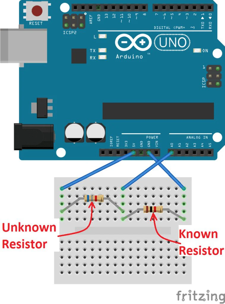
| Connection | Description |
|---|---|
| R_x (unknown) | Between 5V and A0 |
| R_known (e.g. 1 kΩ) | Between A0 and GND |
| A0 | Junction between R_x and R_known |
Hands-onStep 2 — Arduino Code
const int analogPin = A0;
const float Vin = 5.0;
const float R_known = 1000.0;     // known resistor in ohms

void setup() {
  Serial.begin(9600);
}

void loop() {
  int raw = analogRead(analogPin);
  if (raw == 0) {
    Serial.println(-1);           // nothing connected (open circuit)
  } else {
    float Vout = raw * Vin / 1023.0;
    float Rx = R_known * (Vin / Vout - 1);
    Serial.println(Rx);           // send resistance to Processing
  }
  delay(500);
}vconst typo and added a guard for an open circuit (division by zero).Hands-onStep 3 — Processing Code
import processing.serial.*;

Serial myPort;
float resistance = 0;

void setup() {
  size(400, 200);
  myPort = new Serial(this, Serial.list()[0], 9600);
  myPort.bufferUntil('\n');
}

void draw() {
  background(255);
  fill(0);
  textSize(20);
  text("Measured Resistance:", 50, 80);
  if (resistance < 0) text("no resistor", 50, 120);
  else                text(nf(resistance, 1, 2) + " \u03A9", 50, 120);
}

void serialEvent(Serial p) {
  String val = p.readStringUntil('\n');
  if (val != null) resistance = float(trim(val));
}- ▸Arduino reads the voltage at the midpoint of the divider.
- ▸It calculates the unknown resistance with the rearranged formula.
- ▸The value is sent over serial to Processing.
- ▸Processing displays it in real time with units.
Student tasks
| Level | Task | Goal |
|---|---|---|
| Basic | Display the resistance value as text | |
| Intermediate | Colour the text based on the resistance range | |
| Advanced | Draw a dial / gauge visualization | |
| Challenge | Log multiple measurements and plot a graph |
Troubleshooting
| Problem | Likely cause | Fix |
|---|---|---|
| Shows “no resistor” or a huge value | R_x not connected / open circuit | Check both legs of R_x are in the right rows. |
| Shows ≈ 0 Ω | R_x shorted (both legs in the same row) | Place each leg in a different row. |
| Reading is inaccurate | R_known value in code is wrong | Measure R_known and update the constant. |
| Fluctuating values | Poor breadboard contact | Average 10 readings; press parts in firmly. |
P4 · Exercises
Derive the formula
Starting from V_A0 = V_in · R_known / (R_x + R_known), show step by step that R_x = R_known · (V_in / V_A0 − 1).
Hint: Multiply both sides by (R_x + R_known), then divide by V_A0, then subtract R_known.
From reading to ohms
With R_known = 1 kΩ, Arduino reads raw = 310. Calculate V_A0 and R_x. Which standard resistor is it probably? (1 kΩ, 2.2 kΩ, 3.3 kΩ, 4.7 kΩ)
Debug the textbook
The first edition of this handbook said: “R1 (known) between 5V and A0, R2 (unknown) between A0 and GND” but used the formula R2 = R1 · (Vin/Vout − 1). Using R1 = 1 kΩ and a real unknown of 2.2 kΩ, calculate what the meter would display. What is the correct formula for that wiring?
Hint: First find the real Vout for that wiring: Vout = 5 × 2200 / (1000 + 2200).
Colour by range
Colour the displayed value: green below 1 kΩ, orange 1 kΩ–10 kΩ, purple above 10 kΩ. Also display large values in kΩ (e.g. 4.70 kΩ).
Analog gauge
Draw a semicircular gauge (like an old multimeter) from 0 to 10 kΩ with tick marks every 1 kΩ and a needle pointing at the current value.
Hint: Use arc(cx, cy, d, d, PI, TWO_PI). Map resistance to an angle between PI and TWO_PI.
Accuracy investigation
Measure at least 8 resistors (100 Ω … 100 kΩ) with your Arduino meter and a real multimeter. Calculate the percentage error for each. Plot error vs. resistance. When is your meter most accurate, and why? Propose an improvement (e.g. auto-ranging).
Self-check quiz
- 1. Ohm’s law states…
- AU = I / R
- BU = R · I
- CR = U · I
- DI = U · R
- 2. In this circuit, if R_x gets bigger, V_A0…
- Agets bigger
- Bgets smaller
- Cstays at 2.5 V
- Dbecomes negative
- 3. If R_x = R_known, the reading on A0 is about…
- A0
- B256
- C512
- D1023
- 4. Why does the code check raw == 0?
- ATo save power
- BTo avoid dividing by zero when nothing is connected
- CBecause the ADC starts at 1
- DTo blink the LED
- 5. What does nf(1234.5678, 1, 2) return?
- A"1234"
- B"1234.57"
- C"1.23"
- D"1234.5678"
Reflection
- How does a commercial multimeter measure resistance? Is it similar to your circuit?
- What sources of error did you notice? Which could you reduce?
- Why is it important that a formula matches the actual circuit? Where else in science does this matter?
This project introduced electrical measurement, voltage dividers and real-time display. By combining the Arduino Uno with Processing you built a working ohm meter, practised rearranging formulas, and learned to question whether a formula really matches the circuit in front of you — a core skill for every engineer.
Automatic Irrigation System
A plant that waters itself — sensing, deciding and acting.
Measure soil moisture with a capacitive sensor, switch a water pump through a relay, and combine both into a closed-loop automatic irrigation system with a live Processing dashboard.
- Explain how a capacitive soil moisture sensor works and why it does not corrode.
- Explain what a relay is and why it is needed to switch a pump.
- Use threshold logic to make automatic decisions in code.
- Control an actuator manually from Processing and automatically from Arduino.
- Improve a control system with hysteresis to prevent rapid on/off switching.
- Capacitive sensor:
- Measures how well the soil stores electric charge (permittivity) — water changes this a lot.
- Permittivity:
- How strongly a material responds to an electric field. Water ≈ 80, dry soil ≈ 4.
- Relay:
- An electrically operated switch: a small signal from Arduino switches a separate, more powerful circuit.
- Active-LOW:
- A module that switches ON when its input is LOW (common for relay boards).
- Threshold:
- A limit value at which the system changes its decision.
- Hysteresis:
- Using two thresholds (switch on at one, off at another) so the system does not flicker.
- Closed loop:
- A system that measures the result of its own action and corrects itself.
Required equipment
| Component | Qty | Purpose |
|---|---|---|
| Arduino Uno | 1 | Microcontroller |
| Capacitive soil moisture sensor v1.2 | 1 | Soil moisture measurement |
| Relay module (5 V) | 1 | Pump switching |
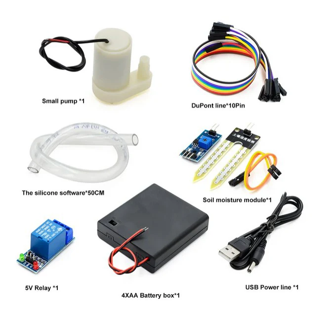
| Small submersible water pump (3–6 V) | 1 | Watering |
| Battery box / external supply matching the pump | 1 | Power for the pump |
| Silicone hose (50 cm) | 1 | Water delivery |
| Breadboard + jumper wires | 1 set | Component connection |
| USB cable + Processing IDE | 1 | Connection & visualization |
TheoryTheoretical Background
How does the soil moisture sensor work?
The capacitive sensor outputs an analog voltage that decreases as moisture increases. Dry soil → high value (~1023 in air, ~600+ in dry soil). Wet soil → low value (~300). Its electrodes are covered, so unlike resistive sensors it does not corrode over time.
The relay module
A relay is an electrically operated switch. A tiny 5 V signal from Arduino controls a separate pump circuit that would be too powerful for an Arduino pin. Many relay boards are active-LOW: input LOW → switch closes → pump ON; input HIGH → pump OFF. Always check your module!
Hands-onExercise 1 — Data Acquisition & Visualization
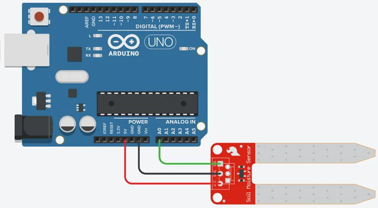
| Sensor pin | Connects to |
|---|---|
| VCC | 3.3V or 5V |
| GND | GND |
| AOUT | Arduino A0 |
const int sensorPin = A0;

void setup() {
  Serial.begin(9600);
}

void loop() {
  int moisture = analogRead(sensorPin);   // ~300 (wet) … ~1023 (dry)
  Serial.println(moisture);
  delay(300);
}import processing.serial.*;
Serial myPort;
int moisture = 0;
void setup() {
size(400, 200);
myPort = new Serial(this, Serial.list()[0], 9600);
myPort.bufferUntil('\n');
}
void draw() {
background(255);
fill(0);
textSize(20);
text("Soil Moisture: " + moisture, 50, 60);
fill(0, 100, 255); // full bar = wet
float w = map(moisture, 1023, 300, 0, 300); // reversed range: low value = wet
rect(50, 100, constrain(w, 0, 300), 30); // adjust 300/1023 after calibration
}
void serialEvent(Serial p) {
String val = p.readStringUntil('\n');
if (val != null) {
val = trim(val);
if (val.matches("\\d+")) moisture = int(val);
}
}Hands-onExercise 2 — Control the Water Pump from Processing
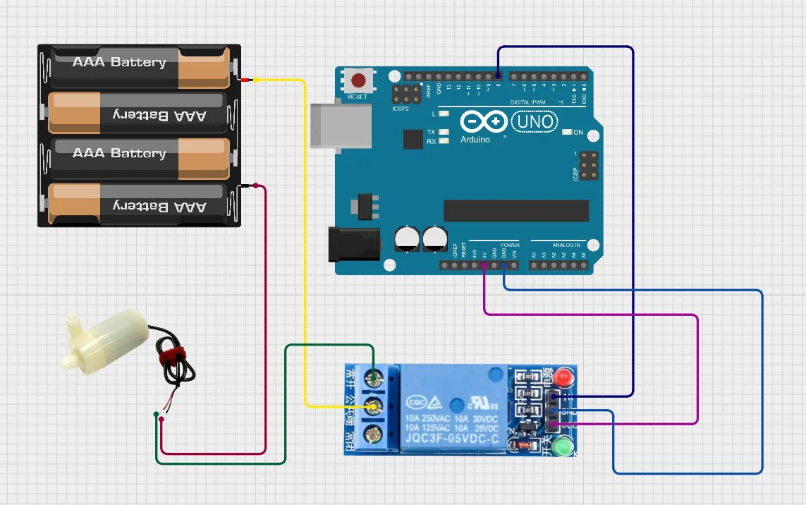
| Connection | Description |
|---|---|
| Relay IN | Arduino D8 |
| Relay VCC | Arduino 5V |
| Relay GND | Arduino GND |
| Relay COM | + terminal of external power supply |
| Relay NO | Pump (+) terminal |
| Pump (−) terminal | Power supply GND |
const int RELAY_PIN = 8;
const int PUMP_ON  = LOW;    // active-LOW relay module
const int PUMP_OFF = HIGH;   // swap these if your module is active-HIGH

void setup() {
  Serial.begin(9600);
  pinMode(RELAY_PIN, OUTPUT);
  digitalWrite(RELAY_PIN, PUMP_OFF);   // make sure the pump starts OFF
}

void loop() {
  if (Serial.available() > 0) {
    char cmd = Serial.read();
    if (cmd == '1')      digitalWrite(RELAY_PIN, PUMP_ON);
    else if (cmd == '0') digitalWrite(RELAY_PIN, PUMP_OFF);
    // any other character (e.g. newline) is ignored
  }
}import processing.serial.*;
Serial myPort;
void setup() {
size(360, 100);
myPort = new Serial(this, Serial.list()[0], 9600);
}
void draw() {
background(200);
fill(0);
text("Press '1' to turn ON pump, '0' to turn OFF", 20, 50);
}
void keyPressed() {
if (key == '1' || key == '0') myPort.write(key);
}ProjectExercise 3 — Full Automatic Irrigation System
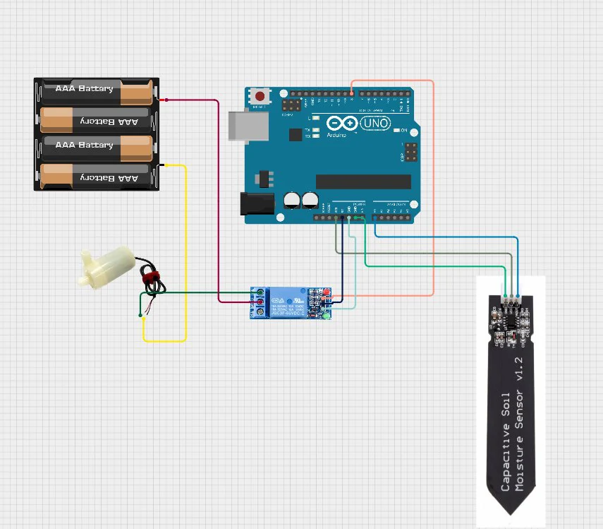
#define RELAY_PIN  8
#define SENSOR_PIN A0
#define THRESHOLD  600       // above = too dry

const int PUMP_ON  = LOW;    // active-LOW relay
const int PUMP_OFF = HIGH;

void setup() {
  Serial.begin(9600);
  pinMode(RELAY_PIN, OUTPUT);
  digitalWrite(RELAY_PIN, PUMP_OFF);
}

void loop() {
  int moisture = analogRead(SENSOR_PIN);
  Serial.println(moisture);

  if (moisture > THRESHOLD) digitalWrite(RELAY_PIN, PUMP_ON);   // dry → water
  else                      digitalWrite(RELAY_PIN, PUMP_OFF);  // wet → stop
  delay(1000);
}import processing.serial.*;
Serial myPort;
int moisture = 0;
void setup() {
size(400, 200);
myPort = new Serial(this, Serial.list()[0], 9600);
myPort.bufferUntil('\n');
}
void draw() {
background(255);
fill(0);
textSize(20);
text("Soil Moisture: " + moisture, 50, 100);
if (moisture > 600) {
fill(255, 0, 0);
text("Status: DRY \u2013 Watering", 50, 140);
} else {
fill(0, 150, 0);
text("Status: WET \u2013 Idle", 50, 140);
}
}
void serialEvent(Serial p) {
String val = p.readStringUntil('\n');
if (val != null && trim(val).matches("\\d+")) moisture = int(trim(val));
}Student tasks
| Level | Task | Goal |
|---|---|---|
| Basic | Display the moisture value and status text | |
| Intermediate | Colour-coded moisture bar (blue = wet, red = dry) | |
| Advanced | Add a manual pump override button in Processing | |
| Challenge | Log moisture data with timestamps to a CSV file |
Troubleshooting
| Problem | Likely cause | Fix |
|---|---|---|
| Pump does not turn on | Relay wiring incorrect or pin mismatch | Relay IN must match RELAY_PIN (8). Listen for the relay “click”. |
| Pump is ON when it should be OFF | Relay is active-HIGH, not active-LOW | Swap the PUMP_ON / PUMP_OFF constants. |
| Sensor always reads max | Sensor not in soil or damaged | Insert up to the line; never submerge the electronics. |
| Pump runs continuously | Threshold too low for your soil | Calibrate: measure dry and wet values and choose a threshold between them. |
| Relay clicks on/off rapidly | Value hovers around the threshold | Add hysteresis (exercise P5.4). |
| Processing shows no data | Wrong COM port or baud rate | printArray(Serial.list()) and use 9600 on both sides. |
P5 · Exercises
Calibrate to percent
Your sensor reads 820 in dry soil and 340 in freshly watered soil. Convert a reading of 580 into a moisture percentage (0 % = dry, 100 % = wet). Write the Processing map() call.
Why a relay?
An Arduino pin can supply about 20 mA at 5 V. A small pump needs about 200 mA. Explain why we can’t connect the pump directly to a pin, and what the relay does instead.
Manual override button
Add an on-screen WATER NOW button to the Processing dashboard that sends 1 while held and 0 when released. Show the pump state with an icon or colour.
Hint: Use mousePressed() and mouseReleased(); check the mouse is inside the button rectangle.
Add hysteresis
With a single threshold the relay can click on and off every second when the value hovers around 600. Change the Arduino code so the pump turns ON above 650 and only turns OFF below 450. Explain why this is better for the pump and the plant.
The thirsty pump
A team’s pump runs all the time, even in wet soil, and stops only when the soil is dry. Their code is the original Exercise 3 with HIGH = water ON. What is wrong, and how do you prove it with a single test?
Water-saving study
Run two identical plants for one week: one watered by hand daily, one by your automatic system. Measure the water used (fill the reservoir to a mark, measure refills) and log moisture. Present which method uses less water and keeps moisture more stable.
- Define fair-test conditions (same plant, pot, soil, location).
- Log moisture every 10 minutes to CSV.
- Record water volume used per day.
- Present a chart and a conclusion with numbers.
Self-check quiz
- 1. As soil gets wetter, the capacitive sensor’s value…
- Aincreases
- Bdecreases
- Cstays the same
- Dbecomes negative
- 2. What is the main job of the relay?
- AMeasure moisture
- BLet a small Arduino signal switch the pump’s separate power circuit
- CStore water
- DIncrease the voltage of the Arduino pin
- 3. An active-LOW relay module turns ON when its input is…
- AHIGH
- BLOW
- Cfloating
- DPWM
- 4. What problem does hysteresis solve?
- AThe sensor corroding
- BRapid on/off switching near the threshold
- CWrong baud rate
- DLow battery
- 5. Which is the safest power choice for the pump in a classroom?
- AMains 230 V
- BA low-voltage battery pack matching the pump
- CThe Arduino 5V pin directly
- DA car battery
Reflection
- Your system is a “closed loop”. Find two other closed-loop systems in everyday life.
- What could go wrong if the sensor fails while the pump is ON? How could you design a safety timeout?
- How could automatic irrigation help farmers in regions affected by drought?
You built a practical automatic system that senses, decides and acts. Combining a soil moisture sensor, a relay and Processing, you gained hands-on experience in electronics, programming and environmental monitoring — the same principles behind smart greenhouses and precision agriculture that help conserve water worldwide.
Appendix A — Answer key
Try every exercise before you look here. For open-ended design tasks, the key describes what a strong answer contains.
F1 · First Steps with Arduino
The LED flashes briefly (on for 0.2 s, off for 0.8 s). One cycle lasts 200 + 800 = 1000 ms = 1 s, so it flashes 60 times per minute. The duty cycle (time on ÷ total time) is 20 %.
R = (5.0 − 3.0) / 0.010 = 200 Ω. The closest standard value that is not smaller is 220 Ω — the current will then be (2.0 / 220) ≈ 9.1 mA, which is safe.
const int ledPin = 8;

void flash(int ms) {
  digitalWrite(ledPin, HIGH);
  delay(ms);
  digitalWrite(ledPin, LOW);
  delay(200);
}

void setup() {
  pinMode(ledPin, OUTPUT);
}

void loop() {
  for (int i = 0; i < 3; i++) flash(200);  // S
  for (int i = 0; i < 3; i++) flash(600);  // O
  for (int i = 0; i < 3; i++) flash(200);  // S
  delay(2000);
}1) Missing semicolon after const int ledPin = 8. 2) pinMode must be OUTPUT, not INPUT. 3) ledpin ≠ ledPin — names are case-sensitive.
const int ledPin = 8;
const int buttonPin = 2;

void setup() {
  pinMode(ledPin, OUTPUT);
  pinMode(buttonPin, INPUT_PULLUP);
}

void loop() {
  bool pressed = digitalRead(buttonPin) == LOW;
  digitalWrite(ledPin, pressed ? HIGH : LOW);
}const int RED = 10, YELLOW = 9, GREEN = 8;
void lights(bool r, bool y, bool g, int ms) {
digitalWrite(RED, r);
digitalWrite(YELLOW, y);
digitalWrite(GREEN, g);
delay(ms);
}
void setup() {
pinMode(RED, OUTPUT);
pinMode(YELLOW, OUTPUT);
pinMode(GREEN, OUTPUT);
}
void loop() {
lights(0, 0, 1, 4000); // green
lights(0, 1, 0, 1000); // yellow
lights(1, 0, 0, 4000); // red
lights(1, 1, 0, 1000); // red + yellow
}F2 · Processing — Real-Time Visualization
a) 512 × 300 / 1023 ≈ 150.1 px · b) 25 × 255 / 50 = 127.5 · c) (750 − 1023) × 100 / (300 − 1023) = (−273)(100)/(−723) ≈ 37.8 %
The first circle is exactly in the centre. The rectangle is a 20 px strip along the bottom edge. The last circle is centred on the top-right corner, so only a quarter of it is visible.
float x = 100, y = 100, dx = 3, dy = 2;
color c = color(61, 245, 255);

void setup() {
  size(500, 300);
  noStroke();
}

void draw() {
  background(20);
  x += dx;
  y += dy;
  if (x < 15 || x > width - 15)  { dx = -dx; c = color(random(255), random(255), random(255)); }
  if (y < 15 || y > height - 15) { dy = -dy; c = color(random(255), random(255), random(255)); }
  fill(c);
  ellipse(x, y, 30, 30);
}1) Baud rate is 115200 but Arduino uses 9600. 2) No background() in draw(), so numbers pile on top of each other (and default fill is drawn on grey — text may be unreadable). 3) readStringUntil() can return null — check before trim(). Adding myPort.bufferUntil('\n') in setup() also helps.
import processing.serial.*;

Serial myPort;
int[] vals = new int[100];

void setup() {
  size(600, 300);
  myPort = new Serial(this, Serial.list()[0], 9600);
  myPort.bufferUntil('\n');
}

void draw() {
  background(15);
  stroke(61, 245, 255);
  strokeWeight(2);
  noFill();
  beginShape();
  for (int i = 0; i < vals.length; i++) {
    float x = map(i, 0, vals.length - 1, 20, width - 20);
    float y = map(vals[i], 0, 100, height - 20, 20);   // reversed: bigger = higher
    vertex(x, y);
  }
  endShape();
}

void serialEvent(Serial p) {
  String s = p.readStringUntil('\n');
  if (s == null) return;
  s = trim(s);
  if (!s.matches("\\d+")) return;
  for (int i = 0; i < vals.length - 1; i++) vals[i] = vals[i + 1];
  vals[vals.length - 1] = int(s);
}import processing.serial.*;
Serial myPort;
float px = 0, py = 0;
boolean pressed = false;
void setup() {
size(500, 500);
myPort = new Serial(this, Serial.list()[0], 9600);
myPort.bufferUntil('\n');
}
void draw() {
background(20);
fill(pressed ? color(198, 255, 61) : color(109, 74, 255));
float x = map(px, 0, 1023, 25, width - 25);
float y = map(py, 0, 1023, 25, height - 25);
ellipse(x, y, 50, 50);
}
void serialEvent(Serial p) {
String line = p.readStringUntil('\n');
if (line == null) return;
String[] v = split(trim(line), ",");
if (v.length != 3) return;
for (String s : v) if (!s.matches("\\d+")) return; // reject malformed lines
px = float(v[0]);
py = float(v[1]);
pressed = v[2].equals("1");
}P1 · Temperature & Humidity — DHT11
Real temperature is between 20 °C and 24 °C, humidity between 43 % and 53 %. A freezer (≈ −18 °C) is outside the 0–50 °C range, so the DHT11 is not suitable — a DHT22 (−40…80 °C) would be.
25.0,40.0 → temp 25.0, hum 40.0. · Error line → unchanged (no comma). · 26.1, → split gives ["26.1", ""], length 2, so temp = 26.1 and hum = NaN — a hidden bug! · 27.3,55.0,1 → length 3 → unchanged. Improvement: also check that both parts are not empty.
boolean tempOk = temp >= 20 && temp <= 24;
boolean humOk  = hum >= 40 && hum <= 60;
int bad = (tempOk ? 0 : 1) + (humOk ? 0 : 1);

if (bad == 0)      fill(0, 200, 90);
else if (bad == 1) fill(255, 200, 0);
else               fill(230, 40, 40);
ellipse(440, 40, 40, 40);

fill(0);
textSize(14);
text(bad == 0 ? "Comfortable" : bad == 1 ? "Check climate" : "Uncomfortable", 330, 80);(a) 25 − 40/5 = 17 °C · (b) 18 − 10/5 = 16 °C — very close to the air temperature, so fog or condensation on windows is likely. In Processing: float dew = temp - (100 - hum) / 5.0;
PrintWriter output;

// in setup():
output = createWriter("weather.csv");
output.println("time,temperature,humidity");

// in serialEvent(), after parsing successfully:
String stamp = nf(hour(), 2) + ":" + nf(minute(), 2) + ":" + nf(second(), 2);
output.println(stamp + "," + temp + "," + hum);

void keyPressed() {
  if (key == 's') {   // press S to save and stop
    output.flush();
    output.close();
    exit();
  }
}Open-ended. A good report includes: a clear hypothesis, a description of the method (sensor position, interval), a chart with labelled axes and units, averages compared in a table, a discussion of sensor accuracy (±2 °C / ±5 %) and a practical recommendation.
P2 · Light Sensor — Photoresistor (LDR)
(a) 5 × 10/11 = 4.55 V → ≈ 930 · (b) 5 × 10/20 = 2.50 V → ≈ 512 · (c) 5 × 10/110 = 0.45 V → ≈ 93
The behaviour is inverted: bright light now gives a low reading and darkness a high one, because V_A0 = 5 × R_LDR / (R_LDR + R_fixed).
const int sensorPin = A0;
const int ledPin = 9;
const int THRESHOLD = 300;

void setup() {
  Serial.begin(9600);
  pinMode(ledPin, OUTPUT);
}

void loop() {
  int light = analogRead(sensorPin);
  bool dark = light < THRESHOLD;
  digitalWrite(ledPin, dark ? HIGH : LOW);
  Serial.println(light);
  delay(200);
}void loop() {
int light = analogRead(A0);
int brightness = map(light, 0, 1023, 255, 0);
analogWrite(9, constrain(brightness, 0, 255));
Serial.println(light);
delay(50);
}int lo = 1023, hi = 0;
// in serialEvent(), after lightLevel is updated:
lo = min(lo, lightLevel);
hi = max(hi, lightLevel);
// in draw():
float w = (hi > lo) ? map(lightLevel, lo, hi, 0, 300) : 0;
rect(50, 100, w, 30);
text("calibrated: " + lo + " – " + hi, 50, 170);
void keyPressed() {
if (key == 'r' || key == 'R') { lo = 1023; hi = 0; }
}Open-ended. Use delay(60000) or millis() on Arduino (or a timer in Processing), log with PrintWriter, and plot in Processing or a spreadsheet. Discuss clouds, blinds, artificial lighting, and the direction the window faces.
P3 · Sonar — Ultrasonic Sensor HC-SR04
(a) 1166 × 0.0343 / 2 ≈ 20.0 cm · (b) t = 2 × 200 / 0.0343 ≈ 11 662 µs ≈ 11.7 ms
Every reading will be exactly twice the real distance, because the measured time covers the path to the object and back.
0 °C: v = 331.3 m/s → reported = 100 × 343 / 331.3 ≈ 103.5 cm (+3.5 %). · 35 °C: v ≈ 352.5 m/s → reported ≈ 97.3 cm (−2.7 %). Combine with a DHT11 (Project 1) to correct it!
float("distance: 23.4 cm") returns NaN because the text isn’t a number. Fix A (Arduino): send only the number: Serial.println(distance_cm);. Fix B (Processing): extract it: String[] m = match(data, "([0-9.]+)"); if (m != null) distance = float(m[1]);
30°, 60 cm: r = 150 → x = 300 + 150·0.866 ≈ 430, y = 600 − 150·0.5 = 525. · 135°, 100 cm: r = 250 → x = 300 + 250·(−0.707) ≈ 123, y = 600 − 250·0.707 ≈ 423.
import processing.serial.*;

Serial myPort;
int angle = 0;
float distance = 0;
final float MAX_CM = 100;
float R;   // radius in px

void setup() {
  size(800, 450);
  R = width / 2 - 20;
  myPort = new Serial(this, Serial.list()[0], 9600);
  myPort.bufferUntil('\n');
  background(0);
}

void draw() {
  noStroke();
  fill(0, 18);                         // fading trail
  rect(0, 0, width, height);

  translate(width / 2, height - 10);   // radar centre at the bottom
  drawGrid();

  stroke(61, 255, 154);                // sweep line
  strokeWeight(3);
  line(0, 0, R * cos(radians(angle)), -R * sin(radians(angle)));

  if (distance > 0 && distance < MAX_CM) {
    float r = map(distance, 0, MAX_CM, 0, R);
    if (distance < 30)      fill(255, 60, 60);
    else if (distance < 60) fill(255, 210, 60);
    else                    fill(61, 255, 154);
    noStroke();
    ellipse(r * cos(radians(angle)), -r * sin(radians(angle)), 10, 10);
  }

  resetMatrix();
  fill(61, 255, 154);
  textSize(16);
  text("Angle: " + angle + "\u00B0   Distance: " + nf(distance, 0, 1) + " cm", 20, 30);
}

void drawGrid() {
  noFill();
  stroke(61, 255, 154, 90);
  strokeWeight(1);
  for (int cm = 25; cm <= MAX_CM; cm += 25) {
    float d = map(cm, 0, MAX_CM, 0, R) * 2;
    arc(0, 0, d, d, PI, TWO_PI);
  }
  for (int a = 0; a <= 180; a += 30) {
    line(0, 0, R * cos(radians(a)), -R * sin(radians(a)));
  }
}

void serialEvent(Serial p) {
  String data = p.readStringUntil('\n');
  if (data == null) return;
  String[] parts = split(trim(data), ",");
  if (parts.length != 2) return;
  angle = int(parts[0]);
  distance = float(parts[1]);
}P4 · Arduino Ohm Meter with Processing Display
V_A0 (R_x + R_known) = V_in · R_known → R_x + R_known = V_in · R_known / V_A0 → R_x = R_known · V_in / V_A0 − R_known = R_known (V_in / V_A0 − 1) ✓
V_A0 = 310 × 5 / 1023 ≈ 1.515 V → R_x = 1000 × (5 / 1.515 − 1) ≈ 2300 Ω → most likely a 2.2 kΩ resistor (within ±5 %).
Vout = 5 × 2200/3200 = 3.44 V. Wrong formula: 1000 × (5/3.44 − 1) ≈ 455 Ω — completely wrong! For that wiring the correct formula is R2 = R1 · Vout / (Vin − Vout) = 1000 × 3.44 / 1.56 ≈ 2200 Ω ✓. Lesson: always check that the formula matches the circuit.
String label;
if (resistance < 1000) {
  fill(0, 170, 80);
  label = nf(resistance, 1, 1) + " \u03A9";
} else {
  fill(resistance < 10000 ? color(255, 140, 0) : color(130, 60, 200));
  label = nf(resistance / 1000.0, 1, 2) + " k\u03A9";
}
textSize(36);
text(label, 50, 140);void drawGauge(float value, float maxValue) {
float cx = width / 2, cy = height - 30, r = 150;
noFill();
stroke(40);
strokeWeight(3);
arc(cx, cy, r * 2, r * 2, PI, TWO_PI);
strokeWeight(1);
for (int i = 0; i <= 10; i++) { // ticks
float a = map(i, 0, 10, PI, TWO_PI);
line(cx + cos(a) * (r - 12), cy + sin(a) * (r - 12),
cx + cos(a) * r, cy + sin(a) * r);
}
float a = map(constrain(value, 0, maxValue), 0, maxValue, PI, TWO_PI);
stroke(220, 40, 40); // needle
strokeWeight(4);
line(cx, cy, cx + cos(a) * (r - 20), cy + sin(a) * (r - 20));
}Expected result: smallest error when R_x ≈ R_known; errors grow for very small or very large R_x, because V_A0 approaches 5 V or 0 V where one ADC step (≈ 4.9 mV) represents a large change in resistance. Improvement: switch between several known resistors (auto-ranging) and average multiple readings.
P5 · Automatic Irrigation System
(820 − 580) / (820 − 340) × 100 = 240 / 480 × 100 = 50 %. In code: float pct = constrain(map(moisture, 820, 340, 0, 100), 0, 100);
The pump needs ~10× more current than the pin can safely give — it could damage the Arduino. The relay lets the weak Arduino signal switch a separate, stronger power supply, while the two circuits stay electrically separated.
boolean pumping = false;

// in draw():
fill(pumping ? color(61, 155, 255) : color(180));
rect(50, 160, 140, 30, 6);
fill(255);
text("WATER NOW", 65, 182);

void mousePressed() {
  if (mouseX > 50 && mouseX < 190 && mouseY > 160 && mouseY < 190) {
    myPort.write('1');
    pumping = true;
  }
}

void mouseReleased() {
  if (pumping) {
    myPort.write('0');
    pumping = false;
  }
}Between 450 and 650 the system keeps its previous state, so it doesn’t flicker. This reduces wear on the relay and pump, and waters the plant thoroughly instead of in tiny bursts. A home thermostat works the same way.
const int DRY_ON  = 650;
const int WET_OFF = 450;
bool pumpOn = false;

void loop() {
  int moisture = analogRead(SENSOR_PIN);
  Serial.println(moisture);

  if (!pumpOn && moisture > DRY_ON)  pumpOn = true;
  if (pumpOn  && moisture < WET_OFF) pumpOn = false;

  digitalWrite(RELAY_PIN, pumpOn ? PUMP_ON : PUMP_OFF);
  delay(1000);
}Their relay is active-LOW, so HIGH actually switches the pump OFF and LOW switches it ON — the logic is inverted. Test: upload a sketch that only does digitalWrite(8, HIGH) and listen/look: if the pump is off, the module is active-LOW. Fix by swapping the constants.
Open-ended. Strong reports discuss variables controlled, show a moisture-vs-time chart for both plants, compare total water (ml), and reflect on threshold choice, evaporation and sensor placement.
Appendix B — Teacher notes & errata
This edition keeps every lab from the original Digital Challenge handbook. All sketches were reviewed; the table below lists every change to the original code or text so that existing printed copies can be corrected.
Suggested scheme of work
| Module | Lessons | Assessment idea |
|---|---|---|
| F1 Arduino Basics | 2 × 45 min | Traffic light controller |
| F2 Processing Basics | 3 × 45 min | Three-value protocol |
| P1 Weather Station | 2 × 45 min | Classroom climate study |
| P2 Light Meter | 2 × 45 min | Sunrise logger |
| P3 Radar Scanner | 4 × 45 min | Full radar display |
| P4 Ohm Meter | 2 × 45 min | Accuracy investigation |
| P5 Smart Garden | 4 × 45 min | Water-saving study |
Errata
| Where | Issue in the original | What changed |
|---|---|---|
| Processing · Lab 1 | int frameCount = 0; redeclares Processing’s built-in frameCount variable. | Uses a separate counter t. |
| Project 1 · Processing | Sketch was missing import processing.serial.*; and contained HTML entities ('). | Import added; reading moved to serialEvent(); bars and alarm included. |
| Project 2 · Theory | Callout said “R2 is the LDR”, but in the wiring the LDR is on the 5V side. | Formula rewritten as V_A0 = 5 V × R_fixed / (R_LDR + R_fixed). |
| Project 3 · Ex. 2 | Servo sweep used blocking for-loops, so STOP was ignored until a sweep finished. | Non-blocking “one step per loop()” sweep. |
| Project 3 · Ex. 1 & 4 | pulseIn() without timeout can freeze for 1 s when there is no echo. | Timeout of 30 000 µs added. |
| Project 4 · Wiring | Wiring table (known resistor on the 5V side) contradicted the diagram and formula. | Table follows the diagram: unknown 5V→A0, known A0→GND. |
| Project 4 · Arduino | Typo vconst; division by zero when no resistor is connected. | Typo fixed; open-circuit guard sends −1. |
| Project 5 · Ex. 2 | Wiring used D8, code used pin 9. | Consistently D8 with named constants. |
| Project 5 · Ex. 3 | Relay logic (HIGH = ON) contradicted Ex. 2 and the active-LOW explanation. | PUMP_ON / PUMP_OFF constants used everywhere. |
| Project 5 · Equipment | 12 V supply listed, while the kit pump/battery box is low-voltage. | Supply must match the pump rating; safety box added. |
Funded by the European Union. Views and opinions expressed are however those of the author(s) only and do not necessarily reflect those of the European Union or the European Education and Culture Executive Agency (EACEA). Neither the European Union nor EACEA can be held responsible for them. Project 2024-2-RS01-KA210-SCH-000271542.